Polycrystalline silicon reducing furnace and preparation technology of furnace cylinder inner wall functional layer of polycrystalline silicon reducing furnace

A reduction furnace, polysilicon technology, applied in metal material coating process, coating, silicon compound and other directions, can solve the problems of increasing the power consumption of polysilicon production, reducing the reflectivity of the reduction furnace, reducing the product quality, etc., and reducing equipment investment. cost, prolong equipment life and reduce heat loss

Pending Publication Date: 2018-06-01
JIANGSU ZHONGNENG POLYSILICON TECH DEV +1
View PDF8 Cites 1 Cited by
  • Summary
  • Abstract
  • Description
  • Claims
  • Application Information

AI Technical Summary

Problems solved by technology

In addition, the explosively formed composite plate roll-rolling welding forming process used in the preparation of the reduction furnace drum is complicated in process, high in cost, and long in production time. One furnace drum needs about 3 months of preparation time.
When the inner wall of the furnace tube is worn and the roughness increases due to reasons such as falling rods, long-term gaseous reactants or / and products carrying silicon powder on the inner wall of the furnace tube, etc., impurities will be released from the inner wall of the reduction furnace tube and pollute the polysilicon , Reduce product quality, reduce the reflectivity of the reduction furnace at the same time, increase the power consumption of polysilicon production

Method used


Image

  • Polycrystalline silicon reducing furnace and preparation technology of furnace cylinder inner wall functional layer of polycrystalline silicon reducing furnace
  • Polycrystalline silicon reducing furnace and preparation technology of furnace cylinder inner wall functional layer of polycrystalline silicon reducing furnace
  • Polycrystalline silicon reducing furnace and preparation technology of furnace cylinder inner wall functional layer of polycrystalline silicon reducing furnace

Examples


Embodiment 1

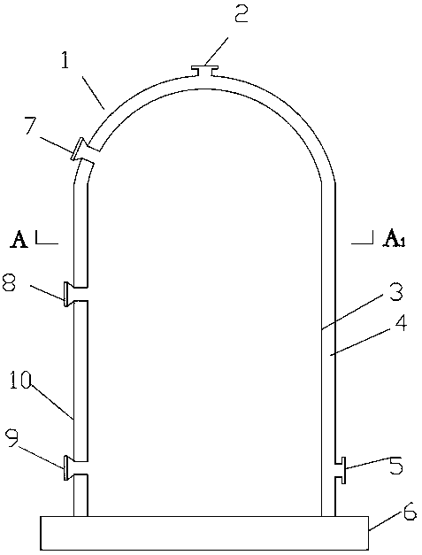
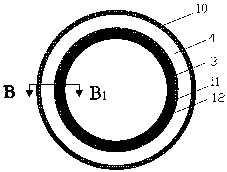
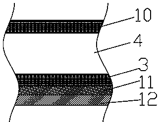
[0031] Such as figure 1 and figure 2 As shown, the polysilicon reduction furnace of the present invention includes a furnace cylinder 1, and the furnace cylinder 1 is installed on the chassis 6. The furnace cylinder 1 is composed of the furnace cylinder inner wall 3 and the furnace cylinder outer wall 10. The furnace cylinder outer wall 10 is connected with the furnace cylinder A water chamber 4 is arranged between the inner wall 3 of the furnace cylinder. At least 3 mirror holes are distributed on the upper, middle and lower parts of the furnace cylinder 1. The mirror holes penetrate the inner wall 3 and the outer wall 10 of the furnace cylinder. There is a cooling medium inlet 5, the upper part of the furnace tube is provided with a cooling medium outlet 2, and the inner wall of the furnace tube 3 is provided with a sandblasting roughening layer 11, and the surface roughness of the sandblasting roughening layer 11 is 80 μm. The roughened sand layer 11 is a structure with i...

Embodiment 2

[0036] Such as figure 1 and figure 2As shown, the polysilicon reduction furnace of the present invention includes a furnace cylinder 1, and the furnace cylinder 1 is installed on the chassis 6. The furnace cylinder 1 is composed of the furnace cylinder inner wall 3 and the furnace cylinder outer wall 10. The furnace cylinder outer wall 10 is connected with the furnace cylinder A water cavity 4 is arranged between the inner wall 3 of the furnace cylinder. The furnace cylinder 1 is distributed with at least 3 sight glass holes along the upper, middle and lower parts of the furnace cylinder. The sight glass holes penetrate the inner wall 3 and the outer wall 10 of the furnace cylinder. 1. The upper part of the desalted water is provided with an upper water inlet 5. The upper part of the furnace cylinder is provided with a cooling medium outlet 2. The inner wall of the furnace cylinder 3 is provided with a sandblasting roughening layer 11. The surface roughness of the sandblastin...

Embodiment 3

[0041] Such as figure 1 and figure 2 As shown, the polysilicon reduction furnace of the present invention includes a furnace cylinder 1, and the furnace cylinder 1 is installed on the chassis 6. The furnace cylinder 1 is composed of the furnace cylinder inner wall 3 and the furnace cylinder outer wall 10. The furnace cylinder outer wall 10 is connected with the furnace cylinder A water cavity 4 is arranged between the inner wall 3 of the cylinder, and at least 3 mirror holes are evenly distributed along the circumference of the furnace cylinder 1. Inlet 5, the upper part of the furnace cylinder is provided with a cooling medium discharge port 2, and the inner wall of the furnace cylinder 3 is provided with a sandblasting roughening layer 11. The surface roughness of the sandblasting roughening layer 11 is 50 μm. Layer 11 is a structure having an irregular concave-convex surface formed by a sandblasting process.

[0042] Wherein said cold medium is preferably desalted water....


PUM

PropertyMeasurementUnit
thicknessaaaaaaaaaa
surface roughnessaaaaaaaaaa

Abstract

The invention discloses a polycrystalline silicon reducing furnace. The polycrystalline silicon reducing furnace comprises a furnace cylinder (1), wherein the furnace cylinder is mounted on a chassis(6); the furnace cylinder comprises a furnace cylinder inner wall (3) and a furnace cylinder outer wall (10); a water cavity (4) is arranged between the furnace cylinder outer wall and the furnace cylinder inner wall; at least three sight glass holes are formed in the upper, middle and lower parts of the furnace cylinder; the sight glass holes pass through the furnace cylinder inner wall and the furnace cylinder outer wall; a refrigerant inlet (5) is formed in the lower part of the furnace cylinder; a refrigerant outlet (2) is formed in the upper part of the furnace cylinder; a sand blast armoring layer (11) is arranged on the furnace cylinder inner wall; a functional layer formed by a nickel-based tungsten alloy and/or a cobalt-based tungsten alloy is arranged on the sand blast armoring layer. The invention further discloses a preparation technology of the functional layer thereof, and the alloy functional layer is coated through a plasma spraying or hypersonic flame spraying technology. According to the polycrystalline silicon reducing furnace used in the invention, the heat loss can be reduced, and the effect of saving 5% to 30% of energy is reached; the specific resistance of polycrystalline silicon is improved; the furnace cylinder inner wall is resistant to wear and long in using time; the furnace cylinder inner wall is convenient to repair, so that the utilization rate of the reducing furnace is improved.

Description

technical field [0001] The invention relates to a reduction furnace, in particular to a polysilicon reduction furnace and a preparation process for a functional layer on the inner wall of a furnace drum, belonging to the technical field of polysilicon reduction furnace preparation. Background technique [0002] High-purity polysilicon is the basic raw material for the electronics and solar photovoltaic industries. Most of the production of polysilicon adopts the improved Siemens process. The main process is: a certain proportion of hydrogen H 2 and high-purity trichlorosilane SiHCl 3 The gas is transported to the polysilicon reduction furnace under a specific pressure, and the vapor deposition reaction is carried out on the conductive silicon rod to generate polysilicon. The reaction temperature is controlled at about 1100°C. Produces silicon tetrachloride SiCl 4 , dichlorodihydrosilane SiH 2 Cl 2 , hydrogen chloride HCl, silicon powder and other by-products. The reacti...

Claims


Application Information

Patent Timeline
Patent Type & Authority Applications(China)
IPC IPC(8): C01B33/035C22C19/07C22C19/05C23C4/129C23C4/134C23C4/06
CPCC22C19/056C22C19/07C23C4/06C23C4/129C23C4/134C01B33/035
Inventor 蒋文武李玉忠张敬亮
Owner JIANGSU ZHONGNENG POLYSILICON TECH DEV
Why Eureka
Try Eureka