Upflow cyclic reoxygenation machine and sewage treatment process using the upflow reoxygenation machine

A kind of reoxygenation machine and body technology, applied in the direction of biological water/sewage treatment, water/sludge/sewage treatment, aerobic process treatment, etc., can solve the problem of high energy consumption, achieve inhibition of anaerobic reaction, reduce energy Consumption, increase the effect of dissolved oxygen

Active Publication Date: 2020-10-20
NINGBO ZHONGHUAN ENVIRONMENTAL PROTECTION TECH
View PDF7 Cites 0 Cited by
  • Summary
  • Abstract
  • Description
  • Claims
  • Application Information

AI Technical Summary

Problems solved by technology

During the operation of the device, there is both energy consumption for raising the water body and aeration energy consumption for the aeration tube, so the energy consumption is too large during operation

Method used


Image

  • Upflow cyclic reoxygenation machine and sewage treatment process using the upflow reoxygenation machine
  • Upflow cyclic reoxygenation machine and sewage treatment process using the upflow reoxygenation machine
  • Upflow cyclic reoxygenation machine and sewage treatment process using the upflow reoxygenation machine

Examples


Embodiment 1

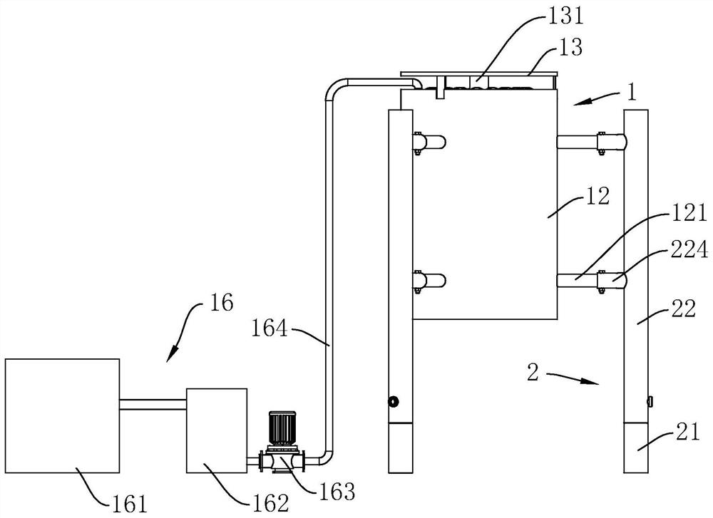
[0046] see figure 1 , an upflow cycle reoxygenation machine, including a base 2 fixed at the bottom of a river and a body 1 slidably connected to the base 2 .

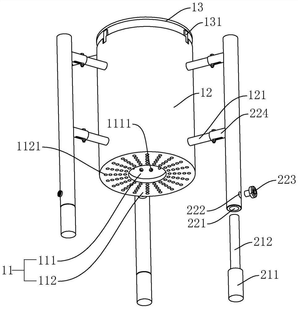
[0047] see figure and figure 2 , the base 2 includes a fixed frame 21 and a sliding frame 22 slidably connected to the fixed frame 21 for connecting the body 1 . The fixed frame 21 includes a fixed seat 211 supported on the bottom of the river and a connecting rod 212 passing through the sliding frame 22 . The sliding frame 22 is provided with a sliding cavity 221 for the connecting rod 212 to slip through and a positioning cavity 222 vertically connected to the sliding cavity 221. The fastening bolt 223 , the end of the fastening bolt 223 abuts against the connecting rod 212 . The sliding frame 22 is also provided with a positioning column 224 for connecting the machine body 1 .

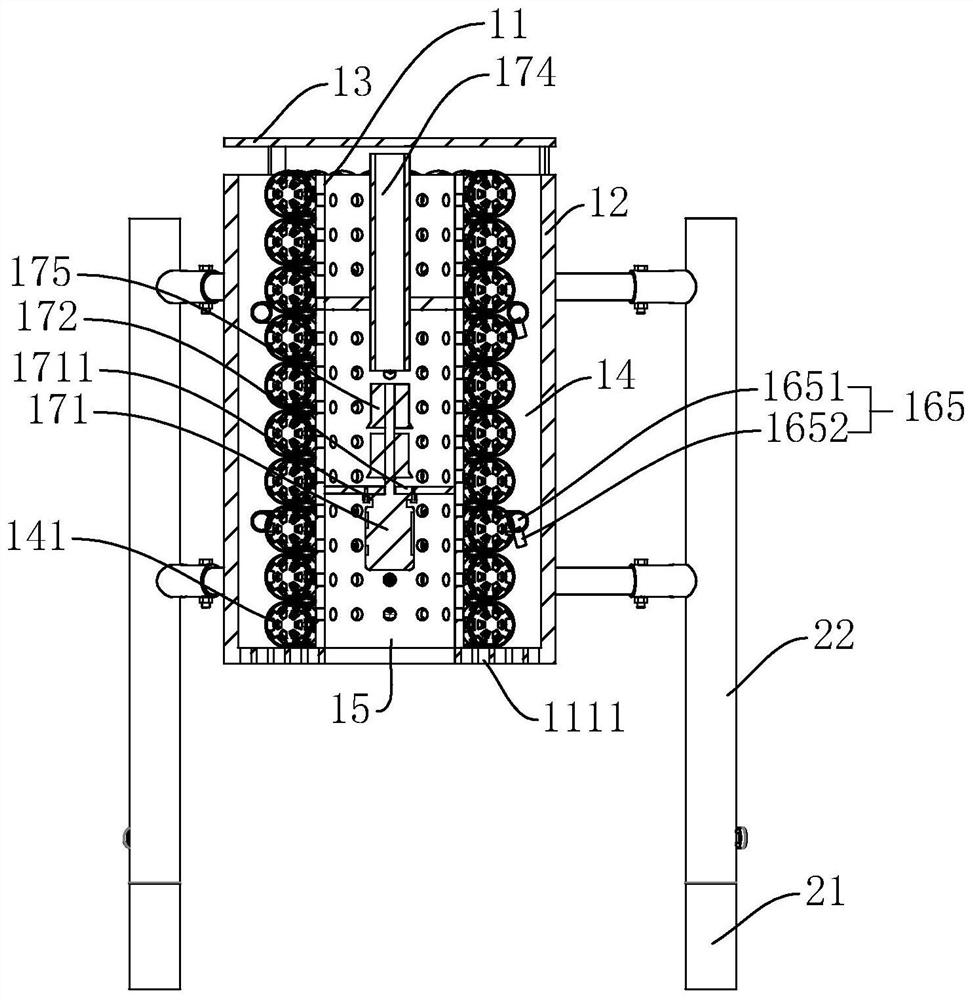
[0048] see figure 2 and image 3 , the body 1 is cylindrical as a whole, and includes an inner body 11 coaxially arranged, an outer...

Embodiment 2

[0059] A sewage treatment process utilizing an upflow recirculation re-aerator, comprising the following steps:

[0060] Step1, fix the upflow re-aeration machine at the bottom of the river, and make one of the openings of the suction pipe above the liquid level;

[0061] Step2, start the driving motor, so that the driving motor drives the centrifugal impeller to rotate to generate negative pressure at the other opening of the suction pipe, and push the water at the bottom of the river away from the bottom of the river;

[0062] Step3, the suction pipe pumps the air to the centrifugal impeller, the gas mixes with the water body at the blade of the centrifugal impeller to form a large number of bubbles, and the bubbles are broken several times under the mechanical cutting of the impeller to form a gas-liquid mixture;

[0063] Step4, the gas-liquid mixture passes through the inner body and diffuses to the outer chamber under the push of the centrifugal impeller;

[0064] Step5,...

Embodiment 3

[0067] The sewage treatment process of embodiment 3 is roughly the same as that of embodiment 2, and the difference is that the surface of the biological filler used in embodiment 3 is pre-loaded with deodorizing microorganisms, and the loading method of deodorizing microorganisms is as follows:

[0068] Step1.1, add 20g of glucose, 20g of peptone, 8g of yeast extract, 4g of potassium dihydrogen phosphate, 4g of dipotassium hydrogen phosphate, and 0.04g of magnesium sulfate into a culture tank with a maximum capacity of 4L. Add water into the culture tank to make up until the inner volume of the culture tank reaches 4L and stir evenly to obtain the microbial nutrient solution;

[0069] Step1.2, add the biological filler into the culture tank, and submerge the microbial nutrient solution into the culture tank for 8 hours;

[0070] Step1.3, intermittently pass sulfur-containing gas into the microbial nutrient solution, the ventilation rate is 1L / min, every 30min, and continue to v...


PUM


Abstract

The invention discloses an up-flow circulating re-oxygenation machine and a sewage treatment process with the same, and solves the problem of high energy consumption of the conventional up-flow circulating re-oxygenation machine. The key point of the technical scheme is that the up-flow circulating re-oxygenation machine comprises an outer machine body fixedly arranged in a river channel, an innermachine body arranged in the outer machine body in a penetrating manner and provided with a through hole, and a machine cover located above the outer machine body in such a manner that a gap is reserved between the machine cover and the outer machine body, wherein the outer machine body and the inner machine body are enclosed to form an outer cavity and an inner cavity, an opening of the outer cavity faces the machine cover, the inner cavity penetrates through the inner machine body, a biological filler is arranged in the outer cavity, a drive motor and an exhaust pipe are fixedly arranged inthe inner cavity, one end of the exhaust pipe faces a motor shaft, an opening in the other end of the exhaust pipe is located above the liquid level, a centrifugal impeller rotating with the motor shaft synchronously is fixedly arranged on the motor shaft of the drive motor, the aeration and the elevating of a water body are integrated, the energy consumption is reduced, the dissolved oxygen at the bottom of the river channel is increased, the anaerobic reaction is inhibited, and the phenomenon of water bloom is further inhibited.

Description

technical field [0001] The invention relates to sewage treatment, in particular to an upflow reoxygenation machine and a sewage treatment process utilizing the upflow reoxygenation machine. Background technique [0002] When algae grow in large numbers, the nutrients in the water are quickly depleted and the algae die. After a large number of algae die, in the process of corruption and decomposition, a large amount of dissolved oxygen in the water will be consumed, and will rise to the water surface to form a layer of green slime, which makes the water body smell bad and causes the phenomenon of "algae bloom"; A large amount of chemical fertilizers are applied along the waters, and domestic sewage and industrial wastewater are discharged into rivers and lakes in large quantities, resulting in an increase in the content of nitrogen, phosphorus, and potassium in rivers and lakes, which will also cause "algae blooms". [0003] The outbreak of "water bloom" caused the lake wate...

Claims


Application Information

Patent Timeline
Patent Type & Authority Patents(China)
IPC IPC(8): C02F3/02C02F3/34C02F101/16
CPCC02F3/02C02F3/34C02F3/347C02F2101/16C02F2101/40C02F2305/06Y02W10/10
Inventor 王云翔
Owner NINGBO ZHONGHUAN ENVIRONMENTAL PROTECTION TECH
Why Eureka
Try Eureka