Wide-range high-precision micro-current measurement system and method

A measurement system and high-precision technology, applied in the direction of using digital measurement technology for measurement, etc., can solve the problems of difficult compensation of thermistors, troublesome selection, and severe compression.

Active Publication Date: 2020-10-23
BEIJING SDL TECH
View PDF6 Cites 0 Cited by
  • Summary
  • Abstract
  • Description
  • Claims
  • Application Information

AI Technical Summary

Problems solved by technology

The general method is to use a pair of tubes made on the same chip to offset the reverse saturation current Is of the middle PN junction, and use a thermistor to compensate the thermal voltage VT, but it is difficult for the thermistor to make the most appropriate compensation in a wide range. Moreover, it is troublesome to choose and match, even if high-precision integrated circuits are used, they will be affected by these factors
In addition, the logarithmic compression method is used, the small signal changes too drastically, and the large signal is compressed very severely. It is difficult to obtain more effective digits in the entire measurement range, especially the large signal part.

Method used


Image

  • Wide-range high-precision micro-current measurement system and method
  • Wide-range high-precision micro-current measurement system and method
  • Wide-range high-precision micro-current measurement system and method

Examples


Embodiment 1

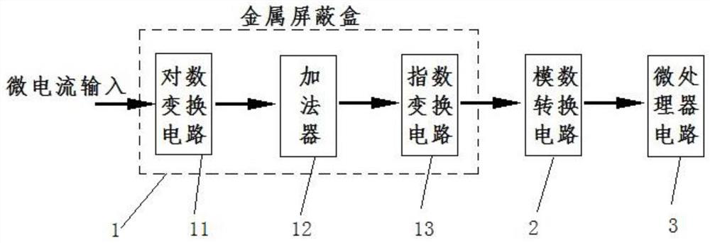
[0081] The present embodiment 1 is a wide-range high-precision micro-current measurement system, such as image 3 As shown, the system includes a multiple square root signal converter 1, an analog-to-digital conversion circuit 2 and a microprocessor circuit 3, and the multiple square root signal converter 1 includes a logarithmic conversion circuit 11, an adder 12, an index Transformation circuit 13. Wherein, the multiple square root signal converter 1 adopts a basic square root signal compression method, such as Figure 5 as shown, Figure 5 It is a basic circuit for multiple square root signal converters in the square root signal compression mode. See Figure 5 , the first operational amplifier U1 and the transistor Q1A, the second operational amplifier U2B and the transistor Q2B all constitute a logarithmic transformation circuit 11, and the output voltage is:

[0082]

[0083] The logarithmic conversion circuit 11 includes an input resistor, an operational amplifier...

Embodiment 2

[0097] Embodiment 2 is a wide-range high-precision micro-current measurement system, such as image 3 As shown, the system includes a multiple square root signal converter 1, an analog-to-digital conversion circuit 2 and a microprocessor circuit 3, and the multiple square root signal converter 1 includes a logarithmic conversion circuit 11, an adder 12, an index Transformation circuit 13. Wherein, the multiple square root signal converter 1 adopts a square root signal improved compression method, such as Figure 6 as shown, Figure 6 An improved circuit for multiple square root signal converters in square root signal compression mode.

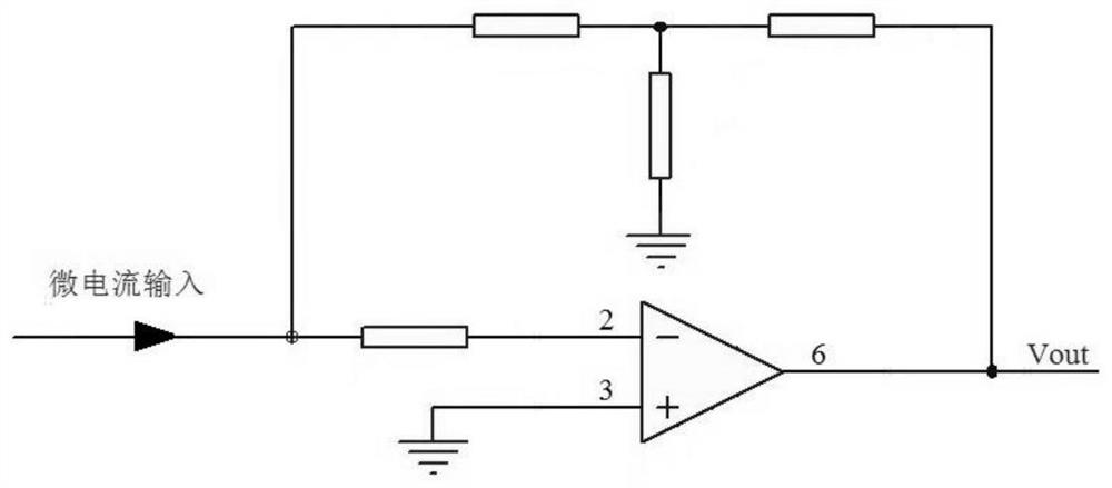
[0098] See Figure 6 , the operational amplifier U1 in the logarithmic transformation circuit of the current measurement part is cleverly used as the adder 12 to simplify the circuit. The collector of the triode Q1A is connected to the inverting terminal 2, and the base is connected to the same-phase terminal 3. Short, so the triode Q1A and...


PUM


Abstract

The invention relates to a wide-range high-precision micro current measurement system and method. The system comprises a multiple root signal converter, an analog-to-digital conversion circuit and a microprocessor circuit, wherein the multiple root signal converter comprises a logarithmic transformation circuit, an adder and an exponential transformation circuit; the logarithmic transformation circuit receives a to-be-measured micro current signal and a reference current signal, and logarithmic transformation is carried out respectively to output two voltage signals to the adder; the adder sums up the voltage signals and the sum is transmitted to the exponential transformation circuit; the exponential transformation circuit receives the sum and carries out exponential transformation, and an analog voltage signal is outputted to the analog-to-digital conversion circuit; the analog-to-digital conversion circuit receives the analog voltage signal, converts the analog voltage signal to a digital signal and transmits the digital signal to the microprocessor circuit; and the microprocessor circuit receives the digital signal, multiple square operation is carried out to restore the valueof a to-be-measured current signal, and current measurement is completed. High measurement precision is achieved in a whole range.

Description

technical field [0001] The invention relates to a micro-current measurement system and method, in particular to a wide-range and high-precision micro-current measurement system and method, which can be applied to the detection field of ion current, photocurrent and other weak currents in various instruments and equipment. Background technique [0002] In instrument measurement, it is often necessary to detect various current signals, such as the current of ion fragments bombarded by the ionization source of a mass spectrometer, the ionization current of a gas chromatograph hydrogen flame, the total ion current converted from vacuum by an ionization vacuum gauge, and weak light signals The generated photocurrent and so on, these current signals are often ranging from "fA" level to "mA" level, not only require extremely weak current detection capability, but also require sufficient measurement resolution in a relatively wide measurement range, so The wide-range weak current me...

Claims


Application Information

Patent Timeline
Patent Type & Authority Patents(China)
IPC IPC(8): G01R19/25
CPCG01R19/25
Inventor 张云
Owner BEIJING SDL TECH
Why Eureka
Try Eureka