Constant-bandwidth broadband filter with electrically-adjusted transmission zero point

A technology of transmission zero point and constant bandwidth, applied in waveguide-type devices, circuits, electrical components, etc., can solve the problem that the filter cannot meet the constant in-band parameters, cannot meet the filter design requirements, and the filter design versatility becomes worse. and other problems, to achieve the effect of improving design efficiency, improving selection performance, and ensuring stable performance

Active Publication Date: 2018-06-01
NO 719 RES INST CHINA SHIPBUILDING IND
View PDF10 Cites 3 Cited by
  • Summary
  • Abstract
  • Description
  • Claims
  • Application Information

AI Technical Summary

Problems solved by technology

However, the transmission zero of a multimode resonator tends to be adjusted as the passband of the resonator is adjusted, and the in-band characteristics will also change accordingly
This point in the filter design will lead to poor filter design versatility, that is, it must be re-selected and designed according to different requirements, which cannot meet the increasing filter design requirements of modern communication systems.
[0004] None of the existing filters can meet the requirements that the in-band parameters are constant, the inherent bandwidth is not affected by other factors, and the filter selection performance can be adjusted and changed through the circuit without affecting the parameters in the passband according to the needs of different scenarios.

Method used


Image

  • Constant-bandwidth broadband filter with electrically-adjusted transmission zero point
  • Constant-bandwidth broadband filter with electrically-adjusted transmission zero point
  • Constant-bandwidth broadband filter with electrically-adjusted transmission zero point

Examples


Embodiment Construction

[0020] In order to describe the present invention more specifically, the embodiments of the present invention will be described in detail below in conjunction with the accompanying drawings.

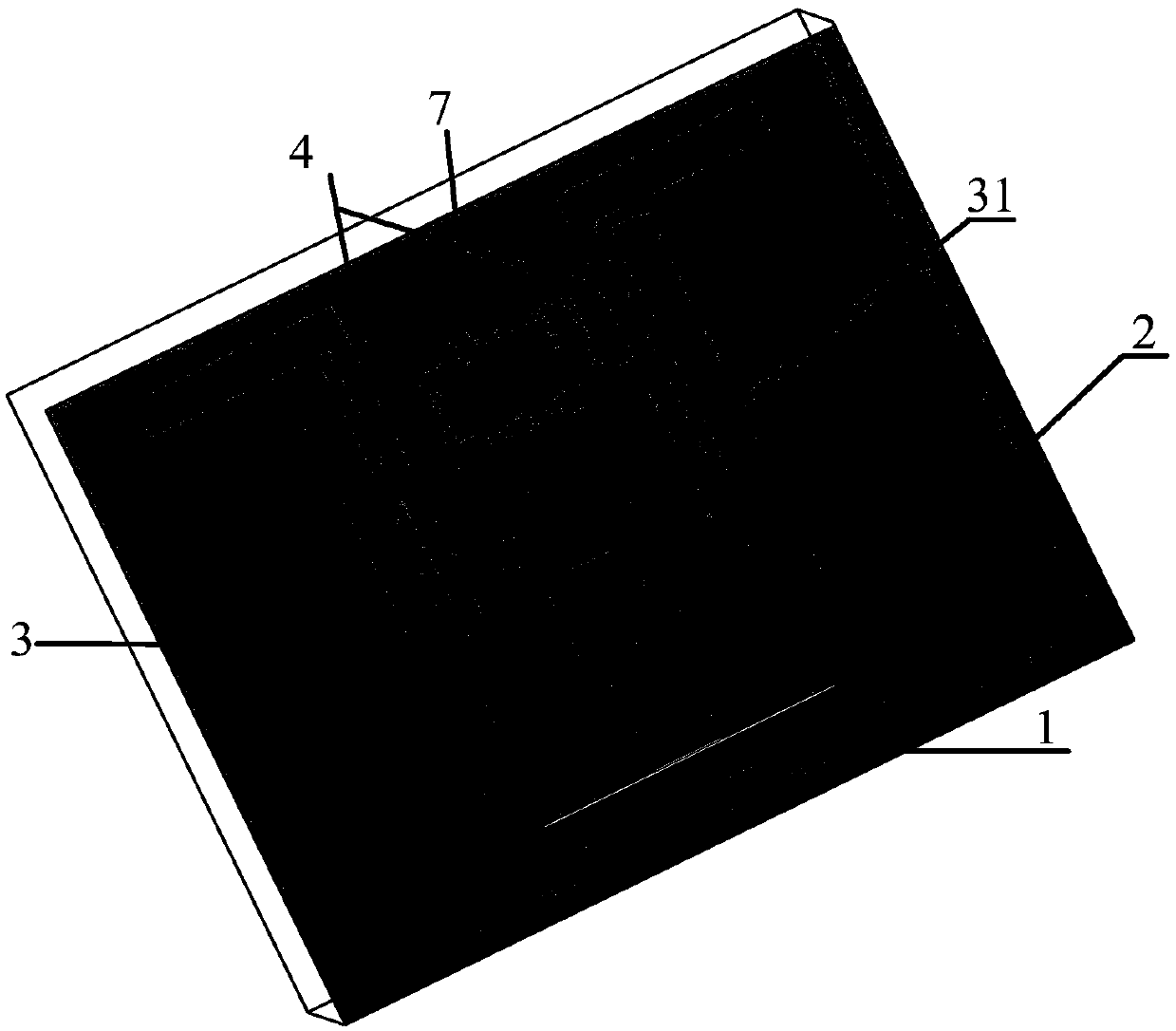
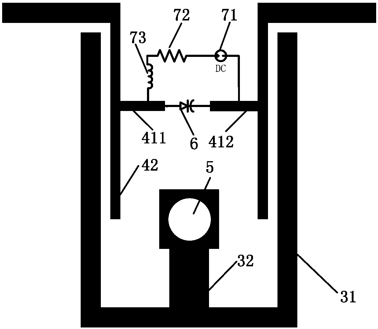
[0021] refer to figure 1 , the present invention is mainly composed of a microstrip dielectric substrate 1, a metal ground plate 2, a short-circuit stub loaded resonator 3, a coupling feeder 4, a ground hole 5, a varactor diode 6 and a DC bias circuit 7. in:

[0022] The microstrip dielectric substrate 1 adopts double-sided copper-clad laminate, and the metal ground plate 2 is under the double-sided copper-clad laminate, such as figure 1 As shown; the short-circuit stub loading resonator 3 on the double-sided copper-clad laminate is in a folded structure, including the main stub 31, the loading stub 32 and the grounding hole 5, which together constitute a constant bandwidth of the broadband filter. The two ends of the main branch 31 are bent vertically toward the side of the loading br...


PUM


Abstract

The invention discloses a constant-bandwidth broadband filter with an electrically-adjusted transmission zero point. The constant-bandwidth broadband filter comprises a micro-strip dielectric substrate (1), a metal grounding plate (2), a short-circuit branch loading resonator (3), a coupling feeder line (4), a grounding hole (5), a capacitance variable diode (6) and a DC biasing circuit (7). A folded short-circuit branch loading resonator is adopted to increase a current path, the resonance frequency is reduced, and a folding double-feeder structure is loaded on the inner side, so that the broadband filter is compact in structure and small in size. A capacitance variable diode control source is coupled with a load, and the capacitance value of the capacitance variable diode is adjusted through a direct current bias circuit, so that the position and the quantity of transmission zero points are changed, and the selective performance of the broadband filter is improved. The performance ofthe passband is not affected, and the constant bandwidth is kept, so that the performance stability of the filter is ensured.

Description

technical field [0001] The invention belongs to the technical field of electronic devices, and in particular relates to a micro-broadband filter, which can be used in radio frequency front ends of wireless communication systems and satellite communication systems. Background technique [0002] The vigorous development of global communication technology makes satellite communication, radar tracking, detection guidance and remote sensing technology more and more rely on microwave and millimeter wave technology. With the increasing number of microwave and millimeter wave communication services, spectrum resources are increasingly tight, and frequency band resources are divided more finely, so the requirements for wireless terminal equipment become very stringent. High-performance, miniaturized, low-cost, and easy-to-integrate microwave filters have become a research hotspot in the field of microwave and radio frequency today. Traditional filters, such as Butterworth and Chebys...

Claims


Application Information

Patent Timeline
Patent Type & Authority Applications(China)
IPC IPC(8): H01P1/203
CPCH01P1/20381
Inventor 杨帅耿攀杨文铁左超余定峰徐林张平郑攀峰肖涵琛王建勋孙瑜陈涛魏华明海涛杜兆伟
Owner NO 719 RES INST CHINA SHIPBUILDING IND
Why Eureka
Try Eureka