Damping load reducing sound barrier

A sound barrier and damping technology, which is applied in construction, noise absorption devices, etc., can solve the problems of ethylene-propylene rubber flame retardancy, poor oil resistance and air tightness, poor self-adhesiveness and mutual adhesion of ethylene-propylene rubber, and increased installation time. , to achieve long service life, reduce workload and reduce maintenance costs

Pending Publication Date: 2018-06-08
山东景中景环保科技有限公司
View PDF0 Cites 2 Cited by
  • Summary
  • Abstract
  • Description
  • Claims
  • Application Information

AI Technical Summary

Problems solved by technology

[0006] However, this damping system has the following disadvantages: 1. The structure is complex, which causes a lot of inconvenience to the installation process and increases the time required for installation. 2. The key to the actual damping effect is the EPDM foamed rubber strip. Ethylene-propylene rubber has the following disadvantages: 1) In terms of the viscosity of the rubber compound, although ethylene-propylene rubber has become the most widely used elastomer in the field of non-tire products, it still cannot show its talents in the production of tire products. Rubber has poor self-adhesiveness and mutual adhesion, which is easy to cause delamination. This problem is also one of the biggest problems in the application of ethylene-propylene rubber; 2) The price of raw rubber. At the beginning of the birth of ethylene-propylene rubber, it was given high expectations by rubber people. Because of its low monomer, some people predict that it will become the rubber with the largest amount and the lowest cost in rubber.
But today, the price of ethylene-propylene rubber raw rubber is still higher than people expected, and it is the highest among its large synthetic rubbers (although its price is lower tha

Method used


Image

  • Damping load reducing sound barrier
  • Damping load reducing sound barrier
  • Damping load reducing sound barrier

Examples


Example Embodiment

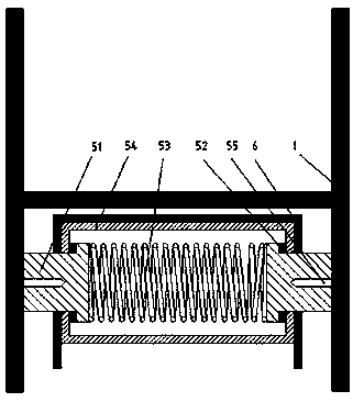
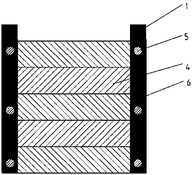
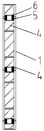
[0030] Figures 1-4 show the second embodiment of the present invention: a damping and load-reducing sound barrier, including a sound barrier screen 4 and H-shaped steel sound barrier pillars 1, on both sides of the sound barrier screen 4 A damping structure is provided between the H-shaped steel sound barrier column 1. The damping structure is arranged between the two sides of the sound barrier screen 4 and the H-shaped steel sound barrier column 1, so that the force is even under the condition of pulsating load. The entire sound barrier screen 4 and the H-shaped steel sound barrier column 1 serve as The whole body bears the pulsating load, the force of each part is uniform, no local damage is caused, and the maintenance cost is reduced. The damping structure is arranged symmetrically on both sides of the sound barrier body 4, which is convenient for installation and mass production. Manufacture, save installation time, improve work efficiency and reduce costs.

[0031] The damp...


PUM

PropertyMeasurementUnit
Thicknessaaaaaaaaaa

Abstract

The invention discloses a damping load reducing sound barrier including a sound barrier body and sound barrier columns, wherein a damping structure is arranged between the two sides of the sound barrier body and the sound barrier columns. The damping structure is a metal damping structure, and the damping structure includes a damping monomer and a damping support. The damping support is made of U-shaped groove steel, and the opening end of the U-shaped groove steel is used to clamp the two ends of the sound barrier body. A damper is arranged in the U-shaped groove steel, the damper comprises asleeve, an inverted-T-shaped connector and a spring, and the sleeve is arranged in the U-shaped groove steel. The damping load reducing sound barrier is simple and novel in structure, convenient to install and long in service life. The material of the damping structure is metal, the practical performance is good, the price is relatively cheap, the cost performance is high, the influence of the environment is very small, the workload of maintenance personnel is reduced, and the maintenance cost is reduced.

Description

technical field [0001] The invention relates to a sound barrier, in particular to a damping load reduction sound barrier. Background technique [0002] With the rapid development of China's economy and the continuous acceleration of urbanization, highways, railways, urban rail transit and other transportation methods have developed rapidly. These roads will inevitably pass through densely populated residential areas during construction, and the traffic noise generated It has brought some interference to the work, life and study of residents near the road. National environmental monitoring results show that: about 17% of cities are moderately polluted in road traffic noise, and 49% are lightly polluted. Building sound barriers to solve traffic noise pollution has become the main way to control urban road noise. [0003] In recent years, my country has built a large number of high-speed railways and put them into operation. In order to solve the noise pollution caused by the ...

Claims


Application Information

Patent Timeline
IPC IPC(8): E01F8/00
CPCE01F8/0011E01F8/0023
Inventor 王晨费城
Owner 山东景中景环保科技有限公司
Why Eureka
Try Eureka