Flue gas pollutant treatment system and treatment method and chimney
A pollutant treatment and pollutant technology, which is applied in the direction of gas treatment, separation methods, chemical instruments and methods, etc., can solve the problems of poor removal effect of low-concentration pollutants, achieve the effect of improving the treatment effect and solving the effect of air pollution
- Summary
- Abstract
- Description
- Claims
- Application Information
AI Technical Summary
Problems solved by technology
Method used
Image

Examples
specific Embodiment 2
[0045] The specific embodiment 2 of the flue gas pollutant treatment system of the present invention, the difference between this embodiment and the above specific embodiment 1 is only: as Image 6 As shown, a humidification device 204 is installed on the top of the wet desulfurization device 200. The humidification device 204 includes a three-stage demisting component 201 and a two-stage atomization layer 202 arranged between the three-stage demisting components 201. The atomization layer 202 passes through Compressed air high-pressure atomization or direct high-pressure atomization, atomization into droplets, atomization particle size can be 10-40μm. The first-stage atomization layer is sprayed with a solution containing a low-concentration sodium-based alkaline desulfurizer, such as sodium carbonate, to achieve humidification of the flue gas while deeply removing low-concentration sulfur dioxide and sulfur trioxide in the flue gas Sulfuric acid mist. The second-stage atomi...
specific Embodiment 3
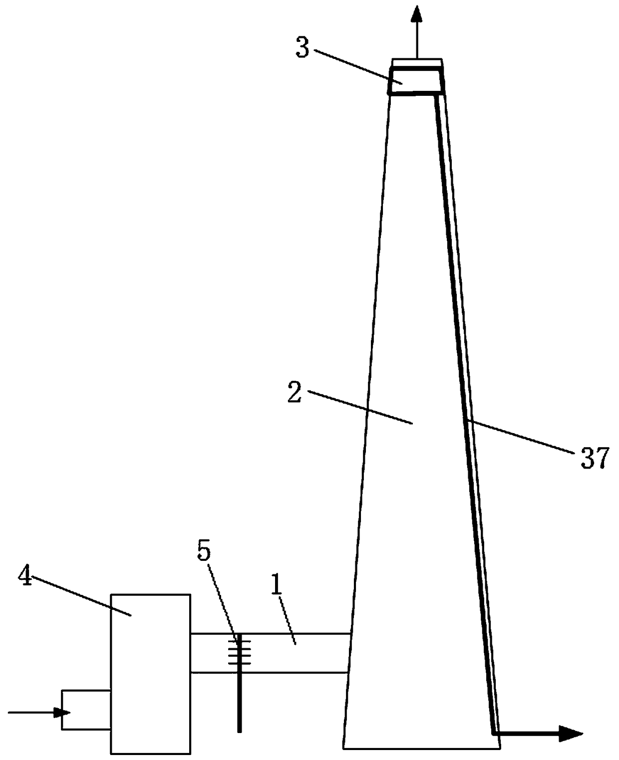
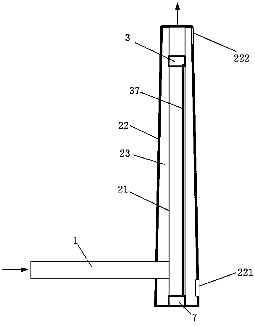
[0047] The specific embodiment 3 of the flue gas pollutant treatment system of the present invention, the difference between this embodiment and the above specific embodiment 1 is only: as Figure 7 As shown, after the pollutant treatment device 301, an atomization layer 303 is arranged at the bottom of the chimney 302 and above the flue gas inlet, and atomized droplets are sprayed in to increase the saturation of water vapor in the flue gas. The atomized liquid droplets can be a solution containing pollutant-removing agents, or liquid water. The atomized liquid droplets collected at the bottom of the chimney 302 can be discharged into the condensate recovery tank together with the liquid droplets collected by the mist eliminator 304 at the top of the chimney 302 .
specific Embodiment 4
[0048] The specific embodiment 4 of the flue gas pollutant treatment system of the present invention, the difference between this embodiment and the above-mentioned specific embodiment 1 is only that the temperature of the flue gas is reduced by the flue gas cooler, and the saturation degree of water vapor is increased, such as Figure 8 As shown, in this embodiment, a heat exchange condensing device is installed in the flue gas pipeline 1 after the pollutant treatment device. The heat exchange condensing device includes a cooler 401 for cooling the flue gas pipeline 1, and the flue gas is reduced by heat exchange and condensation. temperature, realize the humidification of the flue gas, and make the water vapor reach saturation or even supersaturation. The low-temperature cooling fluid and the flue gas flow in the opposite direction and enter the cooler to exchange heat for cooling the flue gas, reduce the temperature of the flue gas, and increase the saturation of the wet flu...
PUM
 Abstract
Description
Claims
Application Information
 - R&D
- Intellectual Property
- Life Sciences
- Materials
- Tech Scout
- Unparalleled Data Quality
- Higher Quality Content
- 60% Fewer Hallucinations
Browse by: Latest US Patents, China's latest patents, Technical Efficacy Thesaurus, Application Domain, Technology Topic, Popular Technical Reports.
© 2025 PatSnap. All rights reserved.Legal|Privacy policy|Modern Slavery Act Transparency Statement|Sitemap|About US| Contact US: help@patsnap.com