
Continuous distribution type optical fiber gas detection device and method

A distributed optical fiber and gas detection technology, which is applied in measurement devices, color/spectral characteristic measurement, analysis of materials, etc. Industrialization implementation and other issues, to achieve the effect of fast and high-precision measurement requirements, high accuracy of results, and simple structure

Pending Publication Date: 2018-06-15
YANCHENG INST OF TECH
View PDF3 Cites 7 Cited by
  • Summary
  • Abstract
  • Description
  • Claims
  • Application Information

AI Technical Summary

Problems solved by technology

Judging from these reports, these inventions are point-type fiber optic gas sensors, which cannot be called distributed fiber optic gas sensors, and the cost of using hollow-core photonic crystal fibers is too high to carry out industrial implementation

Method used


Image

  • Continuous distribution type optical fiber gas detection device and method
  • Continuous distribution type optical fiber gas detection device and method
  • Continuous distribution type optical fiber gas detection device and method

Examples


Embodiment Construction

[0016] The technical solutions of the present invention will be described in detail below, but the protection scope of the present invention is not limited to the embodiments.

[0017] In order to better understand the technical content of the present invention, specific embodiments are given and described as follows in conjunction with the accompanying drawings.

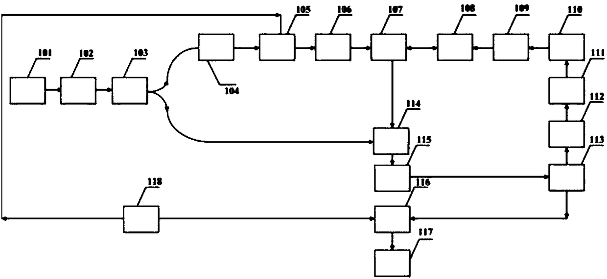
[0018]First laser 101, first isolator 102, first coupler 103, polarization controller, acousto-optic modulator, first erbium-doped fiber amplifier, circulator, sensing fiber, second isolator, second erbium-doped fiber Amplifier, second laser, laser controller, lock-in amplifier, second coupler, photodetector, signal acquisition card, signal processing and display unit 117, the laser signal sent by the first laser enters the first coupler through the first isolator 103, the first coupler divides the laser signal into two beam signals, the first beam signal enters the second coupler 114 as a local oscillator signal, t...


PUM

PropertyMeasurementUnit
diameteraaaaaaaaaa

Abstract

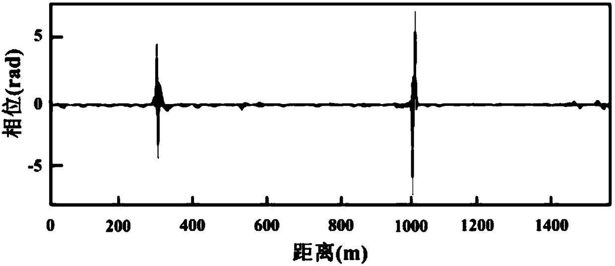
The invention discloses a continuous distribution type optical fiber gas detection device which comprises a first laser, a first separator, a first coupler, a polarization controller, an acoustic optical modulator, a first erbium-doped optical fiber amplifier, a circulator and a sensor fiber which are sequentially connected. The continuous distribution type optical fiber gas detection device is further provided with a second separator, a second erbium-doped optical fiber amplifier, a second laser, a laser controller, a lock-phase amplifier, a second coupler, a photoelectric detector, a signalcollecting card and a signal processing and displaying unit. Some small holes are formed in the sensor fiber to be used as a gas and light interaction area on the sensor fiber, the second laser sendsout signals to serve as pump light to interact with gas in the sensor fiber, the gas can generate a periodic modulation characteristic after absorbing the pump light, and a gas concentration along thesensor fiber can be obtained. The continuous distribution type optical fiber gas detection device disclosed by the invention can achieve high-accuracy gas concentration detection and has the same applicability for varieties of gas detection.

Description

technical field [0001] The invention relates to a gas detection device and method, in particular to a device and method for continuous distributed optical fiber gas detection. Background technique [0002] With the rapid development of my country's economy, the process of industrialization has been rapidly advanced. However, the safety problems brought about by it are very serious. The frequent occurrence of various vicious accidents not only caused personal injury to the relevant practitioners, but also caused serious damage to the country. These accidents basically involve the rapid detection and real-time monitoring of dangerous gases and other related issues. At present, the reported fiber-optic gas sensors are mainly concentrated on point-type fiber-optic gas sensors based on ordinary or photonic crystal fibers, which cannot realize long-distance online gas detection. Therefore, the research and development of distributed fiber-optic gas sensor technology has very import...

Claims


Application Information

Patent Timeline
Patent Type & Authority Applications(China)
IPC IPC(8): G01N21/47G01N21/39
CPCG01N21/39G01N21/47G01N2021/392G01N2021/4709
Inventor 高建军王如刚周锋孔维宾卞金洪卞东
Owner YANCHENG INST OF TECH
Learn More