Starting circuit with low conducting voltage drop

A start-up circuit and low conduction technology, applied in the direction of electrical components, high-efficiency power electronic conversion, output power conversion devices, etc., can solve problems such as large input-output voltage difference, lower Vcc voltage value, lower input power supply voltage, etc., to achieve Meet the input voltage range, the voltage sampling loss is small, and the effect of ensuring normal operation

Inactive Publication Date: 2018-06-15
MORNSUN GUANGZHOU SCI & TECH
View PDF4 Cites 8 Cited by
  • Summary
  • Abstract
  • Description
  • Claims
  • Application Information

AI Technical Summary

Problems solved by technology

However, due to the large voltage drop between the input and output terminals of the voltage clamping circuit itself, the input power supply voltage of the second-stage boost circuit is reduced, resulting in the failure of the second-stage boost circuit to work normally. Finally, when the input voltage is low, no Able to supply power to the control IC normally
[0004] Traditional voltage clamping circuit schemes such as figure 2 As shown (the load is the post-stage step-up circuit), the working principle of the circuit is: the moment the product is powered on, the triode Q1 is turned on, and the emitter current of the triode Q1 rapidly charges the capacitor C2. When the voltage of the capacitor C2 (that is, the startup When the positive output terminal of the circuit provides the voltage of the power supply terminal Vcc of the control IC to the voltage regulation value of the Zener diode D1 minus the conduction voltage drop between the base and the emitter of the transistor Q1, the Vcc voltage will no longer be stable Increase, when the Vcc voltage reaches the working voltage of the booster circuit, the booster circuit starts t

Method used


Image

  • Starting circuit with low conducting voltage drop
  • Starting circuit with low conducting voltage drop
  • Starting circuit with low conducting voltage drop

Examples


no. 1 example

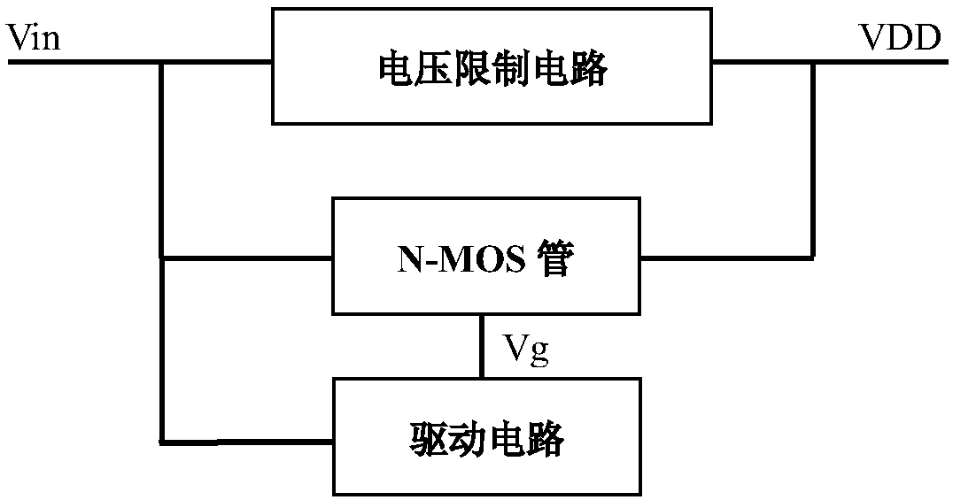
[0038] In the voltage limiting circuit, N-MOS tube and drive circuit of the present invention, the input terminal of the drive circuit is connected to the input voltage Vin, and the input voltage Vin is subjected to voltage sampling to generate a control voltage Vg, and the control voltage Vg is output to the N-MOS tube The gate, the drain of the N-MOS tube are connected to the input voltage Vin, and the source of the N-MOS tube is connected to the subsequent circuit to supply power for the subsequent circuit; the input and output terminals of the voltage limiting circuit are respectively connected to the N-MOS tube of the drain and source.

[0039] For each circuit block, combined with the attached Figure 4 The following specific circuits are used to describe the above three features in detail as follows:

[0040] The N-MOS transistor TR1 is a depletion-type N-MOS transistor, and it can be turned on when the Vgs voltage is greater than a certain negative voltage value VT. ...

no. 2 example

[0052] The difference between this embodiment and the first embodiment is:

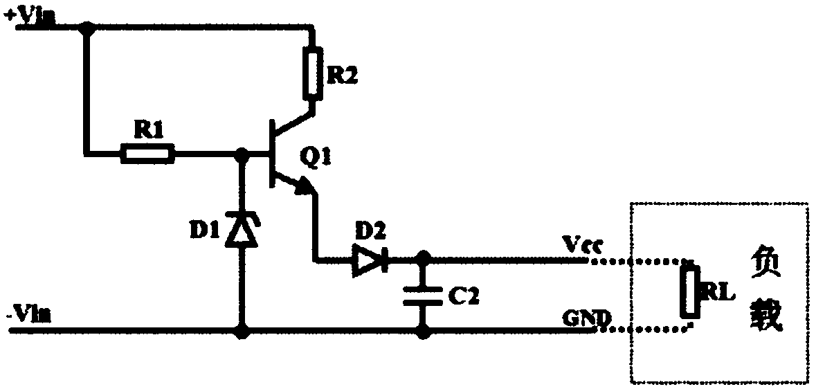
[0053] The voltage limiting circuit is a voltage stabilizing circuit, including a second resistor R2, a third resistor R3, a first NPN transistor Q1, a first capacitor C2 and a second voltage stabilizing diode Z2.

[0054] The second resistor R2 is connected between the input voltage Vin and the C pole of the first NPN transistor Q1, and the third resistor R3 is connected between the input voltage Vin and the B pole of the first NPN transistor Q1; The B pole of the first NPN transistor Q1 is connected to the cathode of the second Zener diode Z2, and the E pole is connected to the output terminal VDD of the driving circuit; the anode of the second Zener diode Z2 is connected to the ground GND; The first capacitor C1 is connected between the output terminal VDD of the driving circuit and the ground GND.

[0055] The regulated voltage value of the first zener diode Z1 needs to be smaller than the regula...


PUM


Abstract

The invention provides a starting circuit with low conducting voltage drop. The input voltage can be detected in real time; when the detected input voltage is lower than a set voltage value, an N-MOStube is switched on, so that the difference between the output voltage and the input voltage of the starting circuit is extremely low, and it is ensured that the starting voltage of a post boost circuit follows the input voltage basically; and when the detected input voltage is higher than the set voltage value, a voltage limiting circuit works, and the output voltage of the starting circuit is limited within the range of working input voltage of the post circuit.

Description

technical field [0001] The invention relates to a starting circuit, in particular to a starting circuit with low conduction voltage drop. Background technique [0002] Start-up circuits are widely used in the field of switching power supplies. In switching power supply products, no matter the primary power supply (AC-DC converter) or the secondary power supply (DC-DC converter), it is necessary to obtain energy from the input terminal and provide a relatively stable power supply voltage for the subsequent control circuit or control IC power supply, so as to drive the switch on and off through the control circuit, and control the inductive device to transfer energy periodically. [0003] In general switching power supplies, in order to solve the problem that when the input voltage is lower than the minimum starting voltage of the control circuit or control IC, the control circuit or control IC cannot be in a normal state because it cannot obtain a high enough power supply vo...

Claims


Application Information

Patent Timeline
IPC IPC(8): H02M1/36
CPCH02M1/36H02M1/0048H02M3/33507Y02B70/10
Inventor 郑典清冯刚李树佳
Owner MORNSUN GUANGZHOU SCI & TECH
Why Eureka
Try Eureka