
Metal interconnect structure and method of forming the same

A technology of metal interconnection structure and device structure, which is applied in the direction of semiconductor/solid-state device parts, semiconductor devices, electrical components, etc., can solve the problems of metal interconnection failure, open circuit, thick insulating layer, etc., to ensure performance and prevent The effect of breaking the circuit and reducing the disc defect

Active Publication Date: 2020-03-31
淮安西德工业设计有限公司
View PDF5 Cites 0 Cited by
  • Summary
  • Abstract
  • Description
  • Claims
  • Application Information

AI Technical Summary

Problems solved by technology

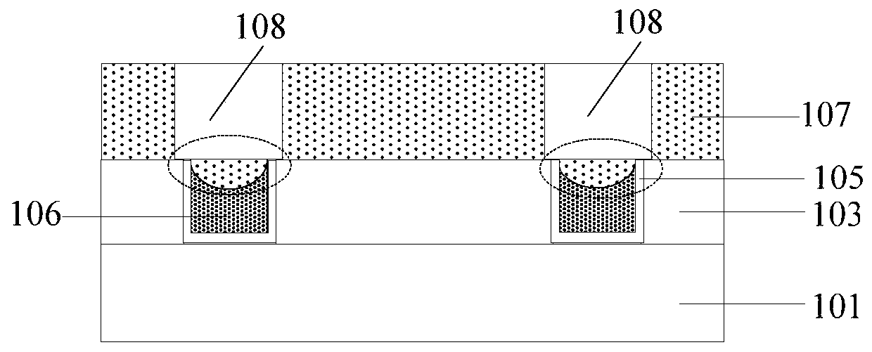
[0003] Currently, in the process of forming the metal interconnection structure of semiconductor devices, disc defects are easily generated when the conductive layer is polished, and when the subsequent insulating layer is deposited, the thickness of the insulating layer is relatively thick at the disc defects. After the etching process Causes the residue of the insulating layer, which in turn causes an open circuit and causes the metal interconnection to fail

Method used


Image

  • Metal interconnect structure and method of forming the same
  • Metal interconnect structure and method of forming the same
  • Metal interconnect structure and method of forming the same

Examples


Embodiment Construction

[0021] It can be seen from the background art that the metal interconnection structure with conductive plugs formed in the prior art has many open circuits, resulting in a problem of low yield of semiconductor devices. Now combine a metal interconnection structure to analyze the reasons for the poor electrical performance between metal interconnection structures:

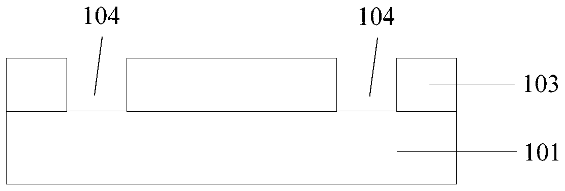
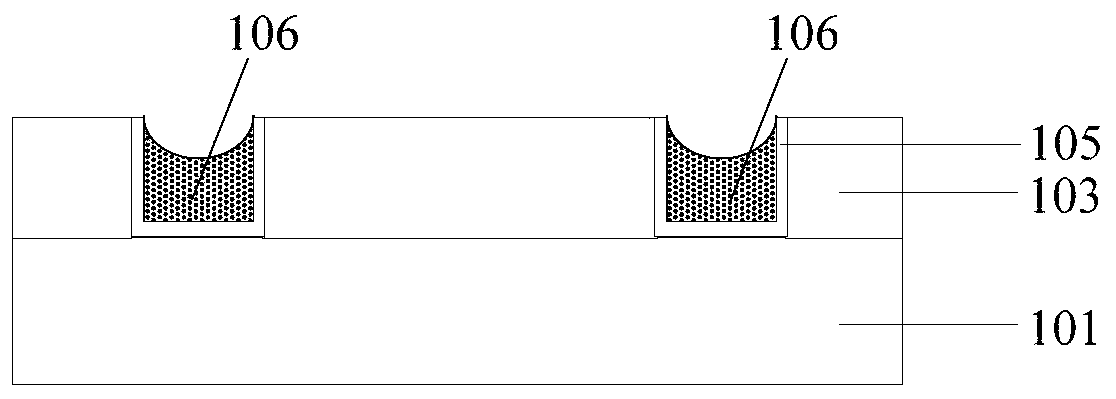
[0022] Figure 1 to Figure 3 A structural diagram corresponding to each step of the method for forming the metal interconnection structure is shown. Such as figure 1 As shown, a first insulating layer 103 is formed on the base layer 101 containing device structures such as driving circuits for isolation between film layers. The material of the first insulating layer 103 can be silicon oxide or silicon nitride; etching The first insulating layer 103 exposes the surface of the base layer 101 to form a contact hole 104 .

[0023] Such as figure 2 shown in figure 1 A barrier layer 105 is formed on the sidewall an...


PUM


Abstract

The technical scheme of the invention discloses a metal interconnection structure and a forming method thereof. The forming method comprises the steps of providing a substrate layer in which a devicestructure is included; forming a first insulating layer on the substrate layer; forming a touch hole, penetrating the thickness of the first insulating layer, in the first insulating layer, wherein the device structure is exposed by the bottom of the touch hole; forming a conductive layer on the surface of the first insulating layer and in the touch hole, and when the width of slot opening in theconducive layer in the touch hole is one tenth to one eighth of the width of the touch hole, stopping forming the conductive layer technology; forming a second insulating layer on the surface of the conductive layer and in the slot; polishing the second insulating layer and the conductive layer by using polishing solution to expose the first insulating layer, and forming a conductive plug, whereinthe rate of polishing the second insulation layer by the polishing solution is less than the rate of polishing the conductive layer. The metal interconnection structure formed by the method effectivereduces disc type defects, and ensures interconnection performance of metal.

Description

technical field [0001] The invention relates to the manufacturing field of semiconductor devices, in particular to a metal interconnection structure and a forming method thereof. Background technique [0002] With the rapid development of semiconductor device manufacturing technology, semiconductor devices already have deep submicron structures. As the number of devices contained in an integrated circuit continues to increase, the size of the device is also continuously reduced due to the improvement of integration. In order to improve the integration level and reduce the manufacturing cost, the key dimensions of the components are getting smaller and the number of components per unit area of ​​the chip is increasing. The vertical space further increases the integration density of the device. [0003] Currently, during the formation of the metal interconnection structure of semiconductor devices, disc defects are easily generated when the conductive layer is polished, and ...

Claims


Application Information

Patent Timeline
Patent Type & Authority Patents(China)
IPC IPC(8): H01L21/768H01L23/538
CPCH01L21/768H01L21/76897H01L23/5386
Inventor 吕新强吴孝哲林宗贤吴龙江郭松辉王海宽
Owner 淮安西德工业设计有限公司
Learn More