
Intracranial pressure sensor, detection equipment and making method

A technology for detecting equipment and internal pressure, applied in pressure sensors, intracranial pressure measurement, sensors, etc., can solve problems such as distortion of measurement results, bleeding, etc., and achieve the effect of small pushing effect, thin thickness, and small volume

Inactive Publication Date: 2018-06-29
INST OF ELECTRONICS CHINESE ACAD OF SCI
View PDF5 Cites 6 Cited by
  • Summary
  • Abstract
  • Description
  • Claims
  • Application Information

AI Technical Summary

Problems solved by technology

[0006] Based on the above problems, the present disclosure provides an intracranial pressure sensor, a detection device and a preparation method to alleviate the problem of existing implantable sensors, which are prone to intracranial hemorrhage due to the use of hard materials, and the measurement results are distorted to a certain extent. technical problem

Method used


Image

  • Intracranial pressure sensor, detection equipment and making method
  • Intracranial pressure sensor, detection equipment and making method
  • Intracranial pressure sensor, detection equipment and making method

Examples


preparation example Construction

[0052] Figure 4 A schematic flow diagram of the preparation method provided in the present disclosure.

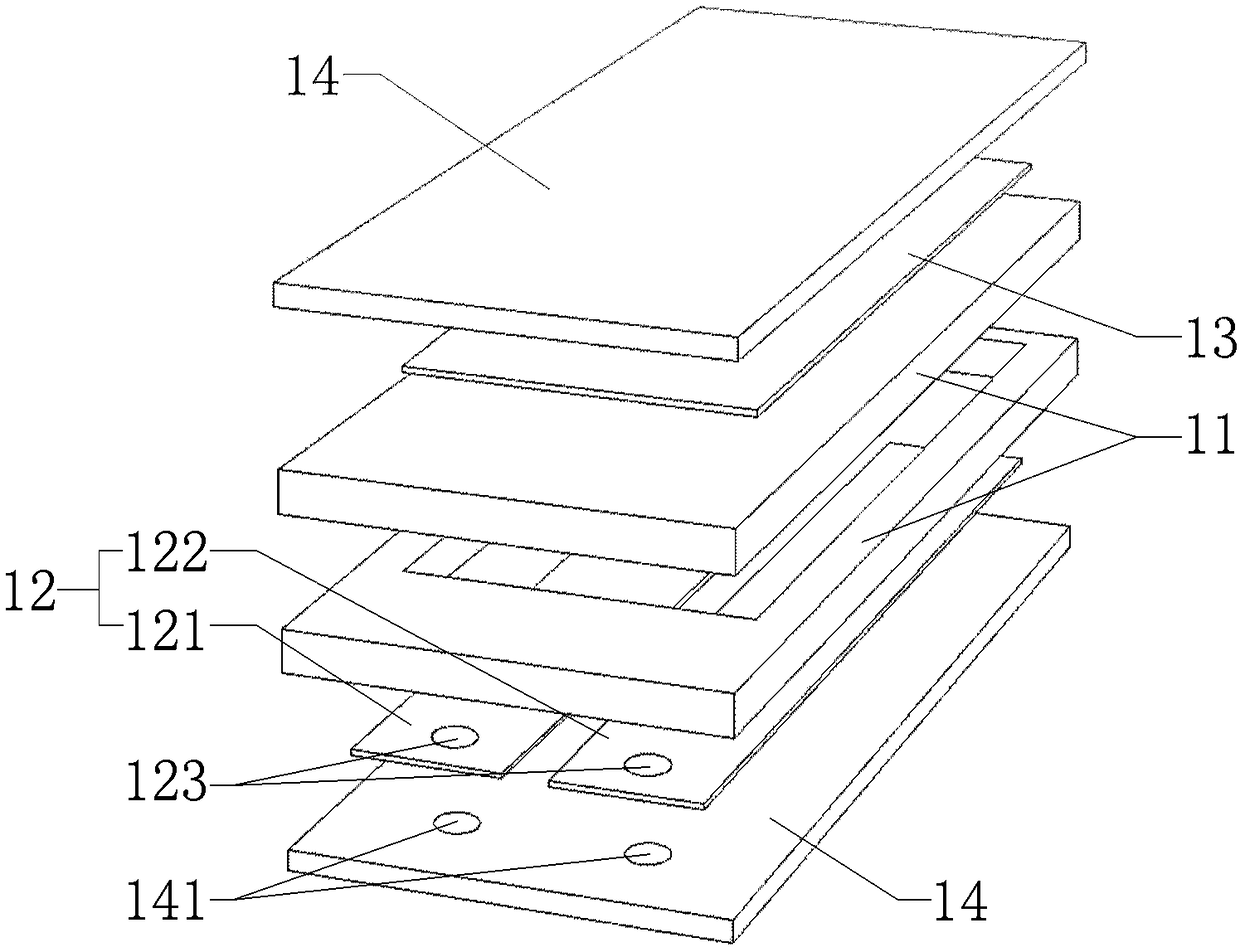
[0053] In yet another exemplary embodiment of the present disclosure, as Figure 4 As shown, a preparation method is also provided, using a MEMS processing technology, including: Step A: depositing Parylene on two glass substrates respectively to form two flexible wrapping layers 14; Step B: forming one of the flexible wrapping layers 14 The first electrode layer 12, the second electrode layer 13 is formed on the other flexible wrapping layer 14; Step C: the first electrode layer 12 and the second electrode layer 13 are oppositely arranged, and the pressure sensitive layer 11 is formed therein; Step D Step E: electrically connect the fixed inductor 20 and the first electrode layer 12 through the wire hole 141 to form an LC oscillating circuit to obtain the intracranial pressure sensor provided by the present disclosure .

[0054] In the present disclosure, step C includ...


PUM

PropertyMeasurementUnit
Inductance valueaaaaaaaaaa
Diameteraaaaaaaaaa
Heightaaaaaaaaaa

Abstract

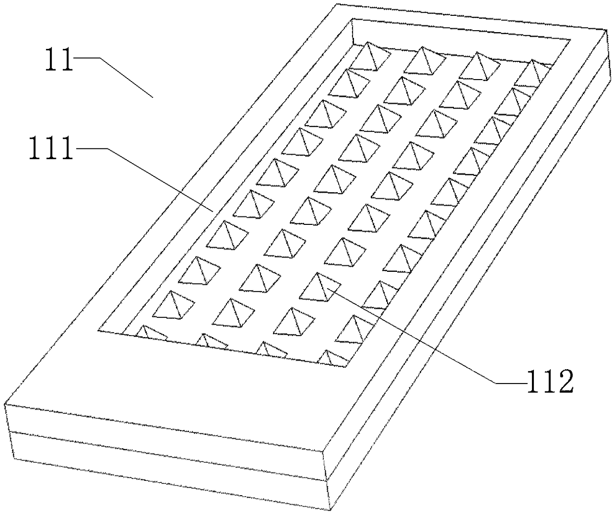
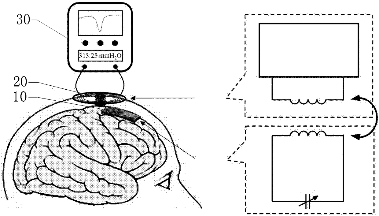
The invention provides an intracranial pressure sensor, which comprises a pressure-sensitive capacitor, a first electrode layer and a second electrode layer, a flexible covering layer, and a fixed inductor, wherein a capacitance value of the pressure-sensitive capacitor varies along with change in intracranial pressure; the pressure-sensitive capacitor comprises a pressure-sensitive layer, and a deformation amount of the pressure-sensitive layer varies along with the change in the intracranial pressure; the first electrode layer and the second electrode layer are formed at two sides of the pressure-sensitive layer, so that a capacitance structure is defined, and a distance between the first electrode layer and the second electrode layer varies along with change in the deformation amount ofthe pressure-sensitive layer; the flexible covering layer covers the outer sides of the pressure-sensitive layer, the first electrode layer and the second electrode layer and is attached between a skull and a dura mater; an LC oscillating circuit is defined by the fixed inductor and the pressure-sensitive capacitor; the fixed inductor is implanted into the skull and is used for converting a capacitance signal into a resonance frequency signal; and the fixed inductor is coupled to external detection equipment and is used for acquiring an intracranial pressure value. A sensor capacitance part which is implanted into the skull is made from a flexible material, so that minimal injury is caused to intracranial tissues, and a risk of such complications as intracranial hemorrhage and the like isreduced to the greatest extent; and the flexible material can get attached to the mater easily, so that more precise measurement is guaranteed.

Description

technical field [0001] The invention relates to the technical field of medical equipment, in particular to an intracranial pressure sensor, a detection device and a preparation method. Background technique [0002] Intracranial pressure is the pressure of brain tissue, cerebrospinal fluid, blood and other cranial cavity contents on the inner wall of the cranial cavity, which is of great significance in the clinical diagnosis of traumatic brain injury and neurology patients. Normal intracranial pressure ranges from 70 to 180 mm H 2 O. Clinically, intracranial pressure exceeds 180 mm H for more than 5 min 2 O is called increased intracranial pressure. Increased intracranial pressure can cause a series of pathological changes in neurology and neurosurgery. The initial manifestations are headache, nausea, vomiting, papilledema, etc.; severe intracranial pressure can also lead to hydrocephalus, brain tumor, meninges, etc. Inflammation and other complications, and even life-thr...

Claims


Application Information

Patent Timeline
IPC IPC(8): A61B5/03
CPCA61B5/031A61B2562/0247
Inventor 王军波魏秋旭陈德勇陈健
Owner INST OF ELECTRONICS CHINESE ACAD OF SCI
Learn More