
Flue gas purifying equipment of kiln

A flue gas purification and equipment technology, which is applied in gas treatment, chemical instruments and methods, electrostatic effect separation, etc., can solve the problems of harmful substance discharge and low treatment efficiency, and achieves low operating costs, reduced work intensity, and good results. Effect

Inactive Publication Date: 2018-06-29
佛山市莫森环境工程有限公司
View PDF5 Cites 2 Cited by
  • Summary
  • Abstract
  • Description
  • Claims
  • Application Information

AI Technical Summary

Problems solved by technology

The treatment efficiency of the traditional kiln flue gas treatment system is not high, and there are still high levels of harmful substances discharged into the atmosphere when discharged. Therefore, it is necessary to provide an efficient kiln flue gas purification equipment

Method used


Image

  • Flue gas purifying equipment of kiln
  • Flue gas purifying equipment of kiln
  • Flue gas purifying equipment of kiln

Examples


Embodiment 1

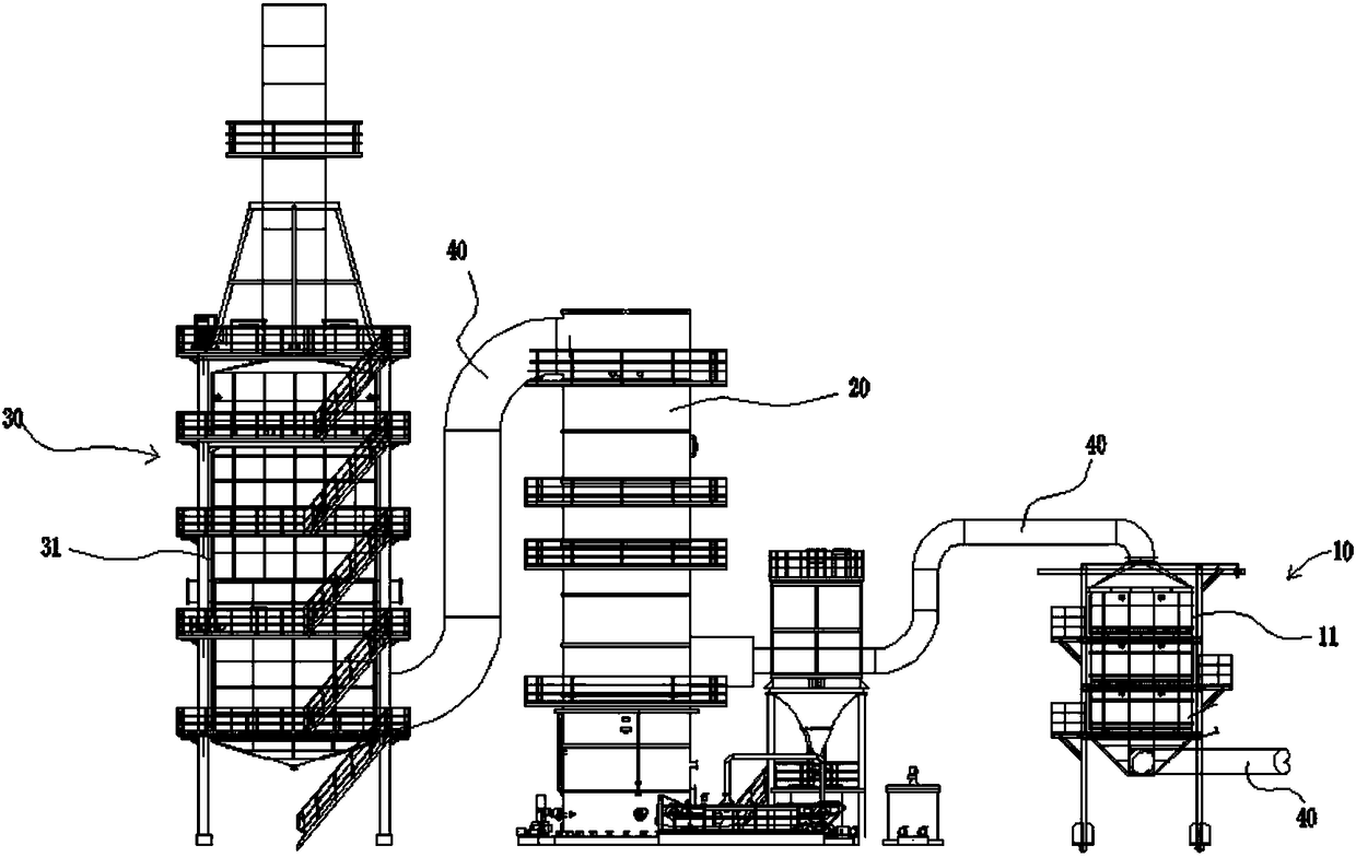
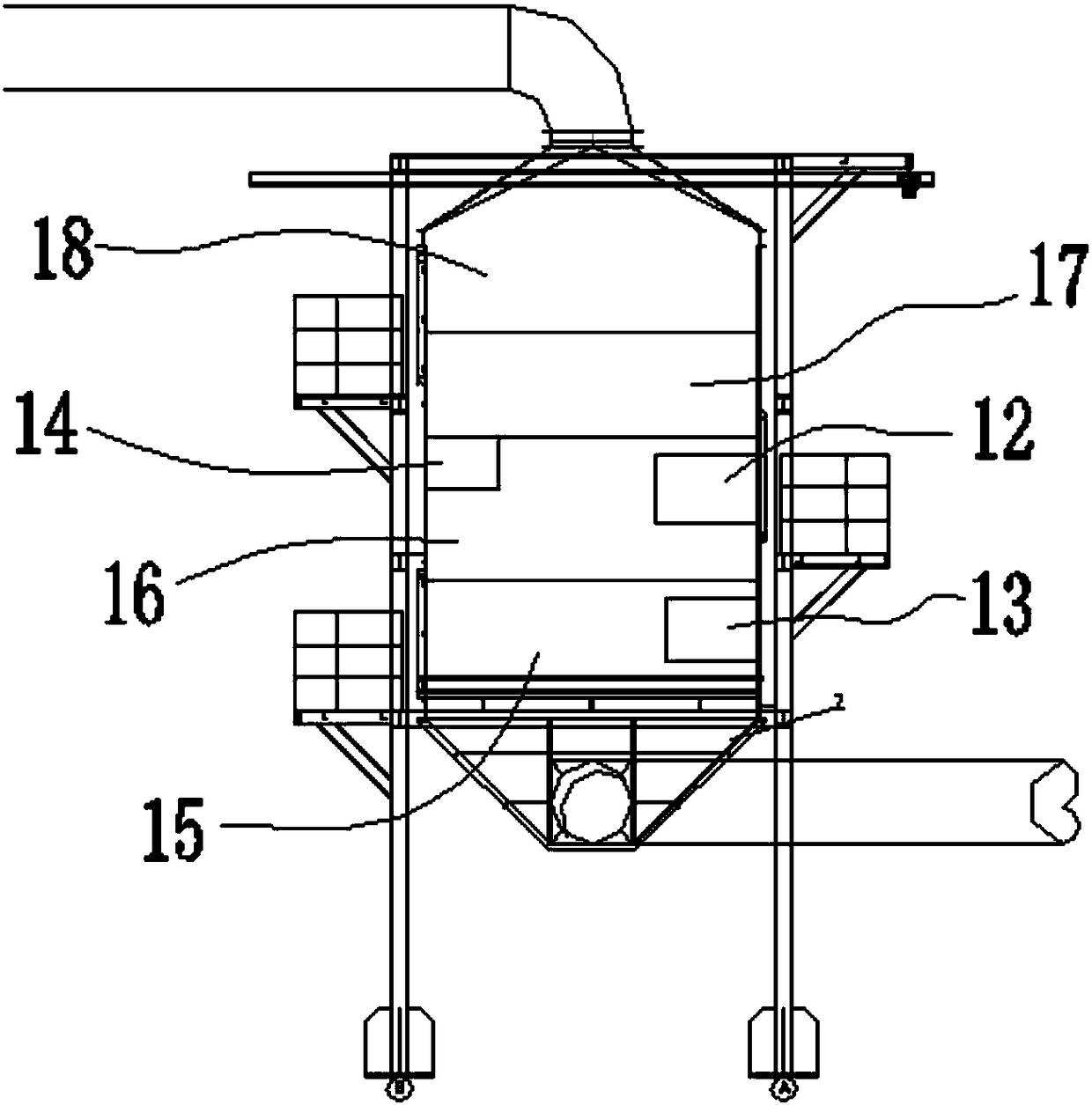
[0012] Such as figure 1 , 2 As shown, the kiln flue gas purification equipment of this embodiment includes low-temperature denitrification equipment 10, desulfurization equipment 20, and wet electrostatic demist and dust removal equipment 30 connected sequentially through the flue gas pipeline 40. The low-temperature denitrification equipment 10 includes a reactor The main body 11, and the reducing agent preparation system 12, the ammonia gas injection device 13 and the catalyst injection device 14 arranged in the reactor body 11, the reducing agent preparation system 12 prepares the reducing agent and mixes it with the flue gas, and the ammonia The gas injection device 13 injects ammonia gas into the flue gas, and the catalyst injection device 14 injects catalyst into the mixed gas of ammonia gas and flue gas; the reactor body 11 is divided into four sections from bottom to top, which are injection Ammonia section 15 , mixing section 16 , flow equalization section 17 and rea...

Embodiment 2

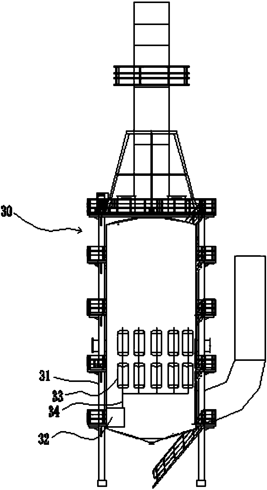
[0018] Such as figure 1 , 2 , 3, the wet electrostatic mist removal and dust removal equipment 30 described in this embodiment includes an electric demister body 31 and a high-voltage electrostatic device 32 arranged in the electric demister 31, and the high-voltage electrostatic device 32 is connected with Several corona wires 34 are respectively inserted into the hollow precipitation tube 33 and are not in contact with the inner wall of the precipitation tube 33 . The working principle is the same as that of the electrostatic precipitator, except that the precipitation electrode adopts a honeycomb tube bundle structure, and each precipitation electrode tube corresponds to a cathode corona wire. During operation, the high-voltage electrostatic device 32 is used to apply negative high-voltage electricity to the corona wire 34 erected in the wet-type electrostatic defogging and dust removal equipment 30, thereby forming an uneven high-voltage electrostatic field between the co...


PUM


Abstract

The invention relates to purifying equipment, in particular to flue gas purifying equipment of a kiln. The flue gas purifying equipment comprises low-temperature denitrifying equipment, desulfurizingequipment and wet type electrostatic demisting and dedusting equipment which are sequentially connected by a flue gas pipeline, wherein the low-temperature denitrifying equipment comprises a reactor body; the reactor body is divided into an ammonia spraying section, a mixing section, a flow equalizing section and a reaction section from bottom to top; an ammonia gas spraying device is arranged atthe ammonia spraying section; a reductant preparation system and a catalyst spraying device are arranged at the mixing section; the wet type electrostatic demisting and dedusting equipment comprises an electric demister body and a high-voltage electrostatic device in the electric demister body; the high-voltage electrostatic device is connected with a plurality of corona wires, and the plurality of corona wires are respectively inserted into hollow deposition electrode pipes and are not in contact with the inner walls of the deposition electrode pipes. The flue gas purifying equipment has theadvantages that the purifying efficiency is high, and the purifying effect is obvious; the 5mg-below superlow emission standard can be reached.

Description

【Technical field】 [0001] The invention relates to purification equipment, in particular to kiln flue gas purification equipment. 【Background technique】 [0002] Nitrogen oxides, collectively referred to as NOx, are one of the main sources of air pollution. The most harmful ones are: NO and NO2. The main hazards of NOx are as follows: (1) toxic to the human body; (2) toxic to plants; (3) can form acid rain and acid fog; (4) form photochemical smog with hydrocarbons; (5) destroy the ozone layer . During the operation of the kiln, a large amount of flue gas will be generated, and it needs to be discharged into the atmosphere. This part of the flue gas contains NOx, SOx, dust and other pollutants, which pollutes the environment. With the environmental protection policies and regulations formulated by the Chinese government, the emission of NOx is strictly limited, and the flue gas containing NOx, SOx and dust is required to be comprehensively treated, including denitrificatio...

Claims


Application Information

Patent Timeline
Patent Type & Authority Applications(China)
IPC IPC(8): B01D53/75B01D53/90B01D53/56B01D53/50B03C3/017
CPCB01D53/50B01D53/75B01D53/8631B01D53/90B01D2251/2062B01D2258/0283B03C3/017
Inventor 颜小辉
Owner 佛山市莫森环境工程有限公司
Learn More