Eureka AIR delivers breakthrough ideas for toughest innovation challenges, trusted by R&D personnel around the world.

Precise Rebound Corneal Dyeing Needle

A technology of dyeing needles and elastic cornea, which is applied in the field of medical devices, can solve the problems of accurate springback corneal dyeing needles that have not been reported, and achieve the effect of simple structure and convenient operation

Active Publication Date: 2020-09-22
SHANGHAI TONGJI HOSPITAL
View PDF8 Cites 0 Cited by
  • Summary
  • Abstract
  • Description
  • Claims
  • Application Information

AI Technical Summary

Problems solved by technology

[0010] But there is no report yet about the precise rebound corneal dyeing needle of the present invention

Method used


Image

  • Precise Rebound Corneal Dyeing Needle
  • Precise Rebound Corneal Dyeing Needle
  • Precise Rebound Corneal Dyeing Needle

Examples


Embodiment 1

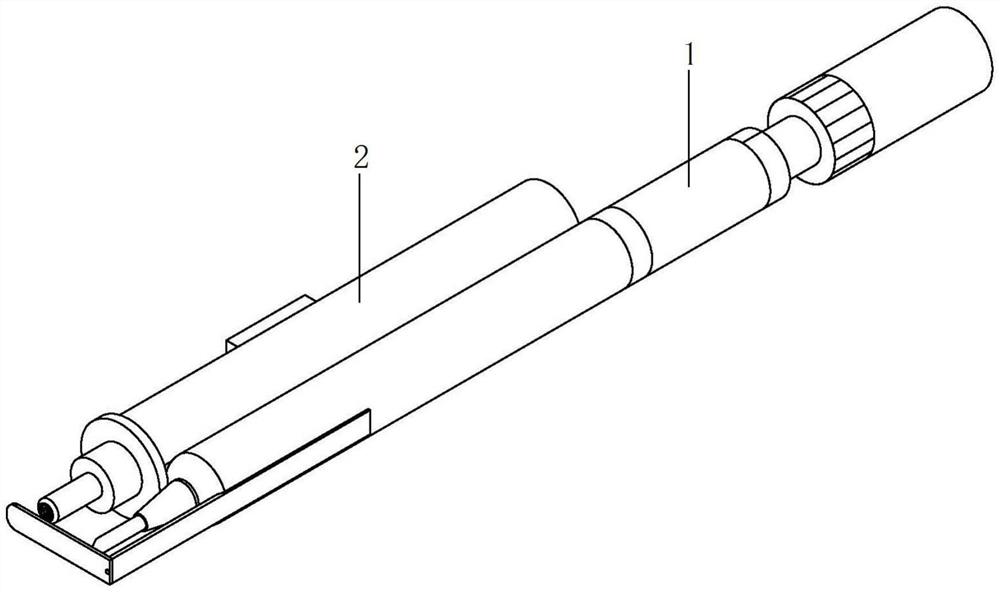
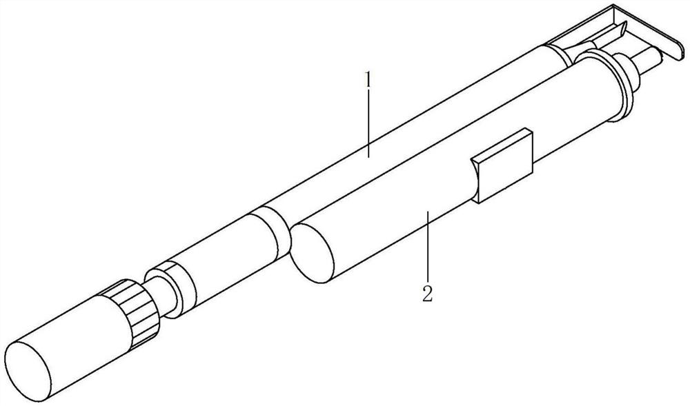
[0054] Please refer to the attached figure 1 , attached figure 2 , attached Figure 7 , with figure 1 , 2 It is a structural schematic diagram of a precise rebound corneal dyeing needle in this embodiment, with Figure 7 It is a schematic diagram of the internal integrated circuit of a precise rebound corneal dyeing needle of the present embodiment. The precise rebound corneal dyeing needle includes a differential dyeing needle 1 , an ultrasonic detection system 2 and an internal integrated circuit 3 .

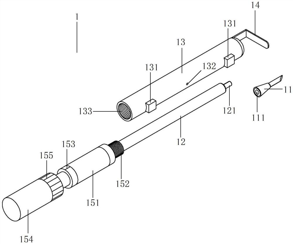
[0055] Please refer to the attached image 3 , attached Figure 5 , attached Figure 6 , with image 3 It is a schematic diagram of the differential dyeing needle structure of a precise rebound corneal dyeing needle in this embodiment, with Figure 5 It is a schematic diagram of the structure of the dyeing needle and the push rod of a precise rebound corneal dyeing needle in this embodiment, with Figure 6 It is a structural schematic diagram of a differential ruler...

Embodiment 2

[0060] Please refer to attached figure 1 , attached figure 2 , attached Figure 7 , with figure 1 , 2 It is a structural schematic diagram of a precise rebound corneal dyeing needle in this embodiment, with Figure 7 It is a schematic diagram of the internal integrated circuit of a precise rebound corneal dyeing needle of the present embodiment.

[0061] The use process and method of the precise rebound corneal dyeing needle:

[0062] First put the dyeing needle 11 on the ordinary syringe, and then use the ordinary syringe to extract a very small amount of dyeing agent into the dyeing needle 11; the inside of the dyeing needle 11 is hollow and can store a very small amount of dyeing agent; then pull out the dyeing needle 11, Through the bushing hole 111, it is set on the bushing 121 on the head of the push rod 12 .

[0063] Ultrasonic sensor 39 and ultrasonic transmitting and receiving circuit 38 are arranged in ultrasonic microprobe 21, can transmit and receive ultraso...


PUM


Abstract

The invention relates to an accurate rebound cornea pigmentation needle which comprises a differential pigmentation needle body, an ultrasonic detection system and an internal integrated circuit. Thedifferential pigmentation needle body comprises a pigmentation needle tip, a push rod, a front end shell, a protective baffle and a differential push ruler; the ultrasonic detection system is composedof an ultrasonic micro-probe, a micro-probe fixing sleeve, a photoelectric encoder, an integrated control board, a power source, a shell and a digital display screen; the internal integrated circuitis arranged in the ultrasonic detection system; the internal integrated circuit is composed of a data storage module, a data display device, an integrated module, a data transmission module, a data processing module, a needle tip telescopic control circuit, a signal processing circuit, an ultrasonic transmitting and receiving circuit, an ultrasonic sensor, a cornea pigmentation needle body and a power supply module. The pigmentation needle has the advantages that the pigmentation needle is simple in structure and convenient to process, and the adjusting precision is up to 100 microns; the length of the extending portion of the cornea pigmentation needle can be adjusted through the change of scales; the cornea pigmentation needle is suitable for corneal pigmentation operations with different corneal pigmentation depths, and prevents cornea penetrating.

Description

technical field [0001] The invention relates to the technical field of medical instruments, in particular to a precision rebound corneal dyeing needle. Background technique [0002] Leukoplakia often results in cosmetic problems secondary to recurrent keratitis, corneal ulceration, or pathological healing of corneal trauma. If the leukoplakia area is located in the visual axis area, it will cause visual loss and even functional blindness. Approaches to treating this disease include functional and cosmetic approaches. When visual reconstruction is ineffective or functional methods cannot be selected, Keratopigmentation (KTP) can be used to stain the leukoplakia to make it look similar to the pupil color to the naked eye, so as to achieve the purpose of changing appearance and increasing self-confidence in life. Currently the most widely used corneal chemical staining agent, such as Indiaink, has been proved to be safe, effective and durable in corneal staining. Keratochrom...

Claims


Application Information

Patent Timeline
Patent Type & Authority Patents(China)
IPC IPC(8): A61F9/007
CPCA61F9/00745
Inventor 毕燕龙高佳妮王桑桑张娟牛国桢张语珊黄心瑜
Owner SHANGHAI TONGJI HOSPITAL
Why Eureka
Eureka Blog
Learn More