Blast furnace slag gas quenching microsphere waste heat recovery device

A technology of waste heat recovery device and waste heat recovery system, which is applied in steam engine devices, recycling technology, furnaces, etc., can solve the problems of large loss of heat energy grade, large water consumption, and difficult to deal with harmful gases, and achieve obvious energy saving and emission reduction. Economic value, the effect of convenient transformation

Pending Publication Date: 2018-07-13
唐山金沙燃烧热能股份有限公司
View PDF8 Cites 4 Cited by
  • Summary
  • Abstract
  • Description
  • Claims
  • Application Information

AI Technical Summary

Problems solved by technology

Disadvantages of water quenching: large loss of thermal energy grade, large water consumption and difficult to deal with harmful gases

Method used


Image

  • Blast furnace slag gas quenching microsphere waste heat recovery device

Examples


Embodiment 1

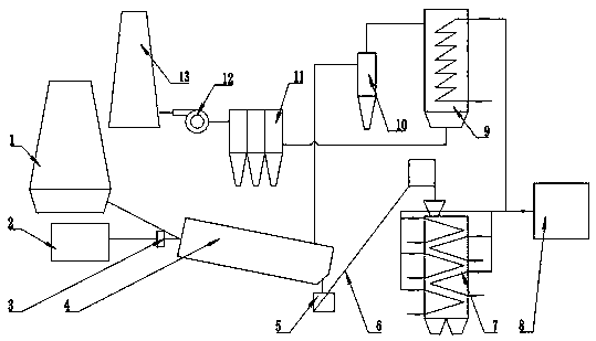
[0021] Example 1: A blast furnace slag gas-quenching microsphere waste heat recovery device, including a gas-quenching granulation system and a waste heat recovery system; the gas-quenching granulation system includes a blast furnace 1, a high-temperature liquid high A gas quenching device 3 for quenching slag into microbeads, a rotary slag solidifier 4 connected to the blast furnace 1 and the gas quenching device 3 for forming and cooling the microbeads, and the waste heat recovery system includes solid-liquid waste heat Boiler 7 and gas-liquid waste heat boiler 9; the top end of the tail of the rotary slag coagulator 4 is connected to the gas-liquid waste heat boiler 9 through a multi-tube dust collector 10, and the bottom of the gas-liquid waste heat boiler 9 is passed through a bag filter 11 and an induced draft fan 12 is connected with the chimney 13, and the hot air generated during the granulation process is purified by the multi-tube dust collector 10 from the tail end ...

Embodiment 2

[0022] Embodiment 2: Further improvement on the basis of Embodiment 1, the gas quenching device 3 includes an air compressor 2, a nozzle, a pipeline pressure regulating valve, an electric control valve, a start regulating valve, a flow meter, a pressure gauge, a high pressure Gas pipes, metal hoses, and flow meters; the nozzles described are Laval nozzles, which can blow high-temperature liquid blast furnace slag gas into microbeads with a particle size of 2 mm; the Mach number of the nozzles is 1.6.

Embodiment 3

[0023] Embodiment 3: Further improvement on the basis of Embodiment 1 or 2, the rotary slag coagulator 4 is lined with heat-insulating and wear-resistant materials, a 1.5m slag-wool separation device is installed at the rear, and a slag is installed in the tail smoke hood. Granular buffer silo.


PUM

PropertyMeasurementUnit
particle diameteraaaaaaaaaa

Abstract

The invention relates to a blast furnace slag gas quenching microsphere waste heat recovery device which comprises a gas quenching pelleting system and a waste heat recovering system. The gas quenching pelleting system comprises a blast furnace, a gas quenching device used for gas quenching of high temperature liquid state blast furnace slag flowing out from the blast furnace into microspheres, and a rotary slag particle solidification device connected with the blast furnace and the gas quenching device and used for molding and cooling the microspheres; the waste heat recovering system comprises a solid-liquid waste heat boiler and a gas-liquid waste heat boiler; the top end of the tail of the rotary slag particle solidification device is connected with the gas-liquid waste heat boiler through a multi-pipe dust removal device, and the bottom of the gas-liquid waste heat boiler communicates with a chimney through a bag-type dust collector and an induced draft fan; and the lower end of the tail of the rotary slag particle solidification device is connected with the top of the solid-liquid waste heat boiler through a slag wool separating system and a slag particle transferring system.The waste heat recovery device special for the blast furnace slag is disclosed, transformation is convenient, high-quality waste heat of a steel mill can be greatly improved, the energy saving and emission reduction effect is obvious, and the high economic benefit is achieved.

Description

technical field [0001] The invention relates to the field of blast furnace slag gas waste heat recovery, in particular to a blast furnace slag gas quenching microbead waste heat recovery device. Background technique [0002] China is currently the world's largest steel producer. China's steel output has been ranked first in the world for 16 consecutive years, and it is far ahead of other countries. At the same time, with the production of blast furnace smelting in my country, the amount of blast furnace slag that is rich in heat energy is also huge. From the perspective of energy saving and environmental protection and improving the economic benefits of steel plants, the heat recovery of blast furnace slag and the resource utilization of blast furnace slag is very necessary. The temperature of blast furnace slag is generally between 1400 and 1550 °C. Each ton of slag contains (1260~1880)×10 3 The sensible heat of kJ is equivalent to the calorific value of 60kg standard co...

Claims


Application Information

Patent Timeline
Patent Type & Authority Applications(China)
IPC IPC(8): C21B3/06F27D17/00C03C13/06F01K25/14F01K27/00
CPCF01K25/14F01K27/00F27D17/004C21B3/06C03C13/06F27D2017/006Y02P10/20Y02P10/25Y02W30/50
Inventor 马宗瑜刘春美郭利亚杨栋杨朋樊学红胡丽丽韩玉杰唐玉婷马怡琳冯铁恒郑晓莲
Owner 唐山金沙燃烧热能股份有限公司
Why Eureka
Try Eureka