Energy-saving and environmental-friendly drying device

A drying equipment, energy saving and environmental protection technology, applied in the direction of drying, dryers, lighting and heating equipment, etc., can solve the problems of reducing material drying efficiency, increasing power consumption, poor energy saving and environmental protection effect, etc., to achieve drying Work convenience, improve utilization rate, good use effect

Inactive Publication Date: 2018-07-17
罗金山
View PDF0 Cites 4 Cited by
  • Summary
  • Abstract
  • Description
  • Claims
  • Application Information

AI Technical Summary

Problems solved by technology

[0004] The dryer has several modes such as belt drying, drum drying, box drying, and tower drying; the heat source includes coal, electricity, gas, etc.; the drying process of materials includes hot air flow type and radiation type, etc. , hot air drum drying is that the hot air flow moves forward from the tail, fully contacts with the material, and makes full use of the heat transfer through heat conduction, convection, and radiation; the heat energy is directly transferred to the material, so that the moisture of the material is continuously evaporated in the cylinder, and the material is fed into the cylinder. The air-introduction device at the outlet draws out a large amount of water and wet air to prevent secondary pollution caused by dust discharge; through internal spiral stirring, sweeping and lifting, the material movement is promoted to complete the entire drying process; countercurrent conduction dehumidification, Avoid reducing repeated drying procedures, but the existing dryers have poor energy-saving and environmental protection effects, which not only increase power consumption, but also reduce the drying efficiency of materials. Therefore, we propose an energy-saving and environmentally friendly drying equipment

Method used


Image

  • Energy-saving and environmental-friendly drying device
  • Energy-saving and environmental-friendly drying device
  • Energy-saving and environmental-friendly drying device

Examples


Embodiment Construction

[0020] The technical solutions in the embodiments of the present invention will be clearly and completely described below in conjunction with the accompanying drawings in the embodiments of the present invention. Obviously, the described embodiments are only a part of the embodiments of the present invention, rather than all the embodiments. Based on the embodiments of the present invention, all other embodiments obtained by those of ordinary skill in the art without creative work shall fall within the protection scope of the present invention.

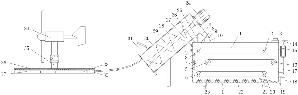
[0021] See Figure 1-4 , An energy-saving and environmentally-friendly drying equipment, including a drying box 1, a screw conveyor box 30 and a battery box 32, the left end of the top of the drying box 1 is fixedly connected with a humidity sensor 26, the top of the drying box 1 and The temperature sensor 8 is fixedly connected to the right side of the humidity sensor 26. The upper end of the inner cavity of the drying box 1 is movably ...


PUM


Abstract

The invention discloses an energy-saving and environmental-friendly drying device. The energy-saving and environmental-friendly drying device comprises a drying tank, a spiral conveying tank and a battery box, wherein a humidity sensor is fixedly connected to the left end of the top part of an inner cavity of the drying tank; a temperature sensor is fixedly connected to the top end of the inner cavity of the drying tank and located on the right side of the humidity sensor; and a first driving wheel and a first driven wheel are sequentially and movably arranged at the upper end of the inner cavity of the drying tank from left to right. According to the energy-saving and environmental-friendly drying device provided by the invention, through the functions of the first driving wheel, the first driven wheel, a second driving wheel, a second driven wheel, a third driving wheel, a third driven wheel, a circulating fan, an air inlet pipe and an air outlet pipe, a displacement distance of a material in the drying tank can be effectively increased, the contact time of the material and hot air in the drying tank is longer, meanwhile, the hot air flow rate in the drying tank can be further improved, the material in the spiral conveying tank can be preheated, and the material drying efficiency is effectively improved.

Description

Technical field [0001] The invention relates to the technical field of drying devices, in particular to an energy-saving and environment-friendly drying equipment. Background technique [0002] Electricity is an energy source powered by electric energy. It was invented in the 1870s. The invention and application of electric power set off the second industrialization climax. It has become one of the three technological revolutions in the world since the eighteenth century. It has changed people’s lives. The large-scale power system that emerged in the 20th century is one of the most important achievements in the history of human engineering science. It is a power production and consumption system composed of power generation, transmission, transformation, distribution, and power consumption. It converts the primary energy of nature into electricity through mechanical energy devices, and then supplies electricity to users through power transmission, transformation and distribution....

Claims


Application Information

Patent Timeline
Patent Type & Authority Applications(China)
IPC IPC(8): F26B15/18F26B21/00F26B25/00F26B25/02H02J7/35
CPCF26B15/18F26B21/004F26B25/001F26B25/02H02J7/35Y02P70/10
Inventor 罗金山
Owner 罗金山
Why Eureka
Try Eureka