High-selectivity compact band-pass filter and design method thereof

A technology of band-pass filter and design method, which is applied in waveguide devices, CAD circuit design, instruments, etc., can solve problems such as poor out-of-band suppression, increased process difficulty and uncertain factors, large insertion loss and volume, etc., to achieve Small size, high out-of-band suppression characteristics and selectivity, effect of improving selectivity

Active Publication Date: 2018-07-17
NANJING PANDA ELECTRONICS +1
View PDF5 Cites 4 Cited by
  • Summary
  • Abstract
  • Description
  • Claims
  • Application Information

AI Technical Summary

Problems solved by technology

But so far, these two types of filters can only achieve Chebyshev (Chebyshev) characteristics at most, that is, the amplitude-frequency characteristics are relatively flat, but the out-of-band suppression is poor
In order to improve this problem, it is often to increase the order of the filter, but increasing the order will introduce greater insertion loss and volume, which cannot alleviate the problem from the root cause, and this approach increases the difficulty of filter design
[0003] For ordinary microstrip crossover filters, due to the requirement of grounding, certain process difficulties and uncertain factors are added
However, the traditional Chebyshev and elliptic function filters have gradually been unable to meet the actual engineering needs due to their many shortcomings, especially in recent years, high temperature superconducting technology (HTS) and monolithic microwave integrated circuit (MMIC) technology The development of the technology makes it necessary to develop a new type of filter with small size, light weight, stable performance and low manufacturing cost.

Method used


Image

  • High-selectivity compact band-pass filter and design method thereof
  • High-selectivity compact band-pass filter and design method thereof
  • High-selectivity compact band-pass filter and design method thereof

Examples


Embodiment Construction

[0042] The method described in the present invention will be further described below in conjunction with the accompanying drawings and specific embodiments.

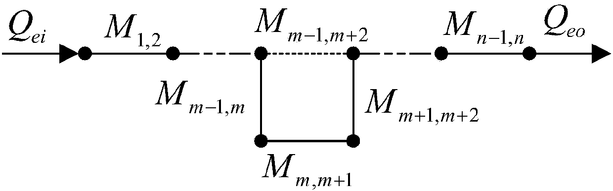
[0043] In order to realize a band-pass filter (abbreviated as the target filter) with a pair of transmission poles, the present invention adopts the design method of the low-pass prototype filter, and utilizes the non-adjacent resonators in the standard Chebyshev filter. cross-coupling to achieve the transfer function pole Ω a the introduction of.

[0044] like figure 1 As shown, in the coupling topology of a bandpass filter with a pair of transmission poles, each node represents a unit resonator, the solid line represents the main coupling, and the dotted line in the middle represents the auxiliary coupling (ie, cross coupling). Coupling coefficient M i,j (that is, the coupling coefficient between the i-th unit resonator and the j-th adjacent unit resonator) and the external quality factor Q ei , Q eo It can be det...


PUM


Abstract

The invention discloses a design method of a high-selectivity compact band-pass filter and the filter obtained through the method. The method includes the steps that the coupling coefficient and external quality factor of a target filter are calculated through a design method of a low-pass prototype filter; the basic size of unit resonators is designed, then, multipoint simulation is conducted forthe spacing between unit resonators in a basic coupled structure to obtain the corresponding relationship of resonant frequencies and spacing points and a fitted curve, and the coupling coefficient and external quality factor corresponding to each spacing point are calculated; a group of coupling coefficient and external quality factor closest to the coupling coefficient and external quality factor obtained by the design method of the low-pass prototype filter are selected from the fitted curve to serve as the coupling coefficient and external quality factor of the target filter, the corresponding spacing value serves as the spacing between the unit resonators in the target filter, and then a final physical structure is determined. In the target filter, by introducing cross coupling to generate a pair of transmission poles, the selectivity of the filter is obviously improved.

Description

technical field [0001] The invention belongs to the technical field of wireless communication, and in particular relates to a design method of a high-selectivity compact band-pass filter and a high-selectivity compact band-pass filter obtained by the method. Background technique [0002] With the rapid development of mobile communication and computer technology, in order to save frequency band resources and improve anti-interference ability, various circuit systems have higher and higher requirements for filter performance. Crossover filter and parallel coupled line filter are two common forms of microstrip filter. But so far, these two types of filters can only achieve Chebyshev (Chebyshev) characteristics at most, that is, the amplitude-frequency characteristics are relatively flat, but the out-of-band suppression is poor. In order to improve this problem, it is generally necessary to increase the order of the filter, but increasing the order will introduce greater insert...

Claims


Application Information

Patent Timeline
Patent Type & Authority Applications(China)
IPC IPC(8): G06F17/50H01P1/203
CPCG06F30/30H01P1/203
Inventor 姚兴强
Owner NANJING PANDA ELECTRONICS
Why Eureka
Try Eureka