Compound desulfurizer and sulfurous gas deep desulfurization method

A desulfurization agent and gas technology, applied in the field of deep desulfurization of sulfur-containing gases, can solve the problems of low catalyst timeliness, large pipeline investment, high anti-corrosion costs, etc., achieve low absorption rate, realize direct emission, and strong adaptability

Inactive Publication Date: 2018-07-20
郝天臻
View PDF5 Cites 4 Cited by
  • Summary
  • Abstract
  • Description
  • Claims
  • Application Information

AI Technical Summary

Problems solved by technology

This process has the advantages of high desulfurization efficiency and low operating cost, but the catalyst has low timeliness and requires fr

Method used


Image

  • Compound desulfurizer and sulfurous gas deep desulfurization method
  • Compound desulfurizer and sulfurous gas deep desulfurization method
  • Compound desulfurizer and sulfurous gas deep desulfurization method

Examples


Embodiment 1

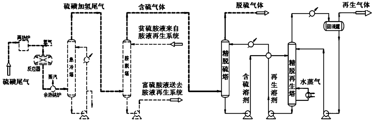
[0061] This embodiment provides a deep desulfurization method for sulfur-containing gas, wherein the sulfur-containing gas comes from the product of sulfur tail gas desulfurized by the SCOT process. The specific process of SCOT process desulfurization is carried out according to the above steps 1 to 5, and the specific process of deep desulfurization is carried out according to the above steps 6 to 8.

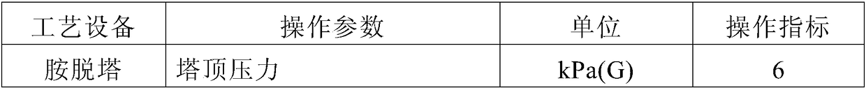
[0062] See Table 1 for specific process parameters of SCOT process desulfurization and deep desulfurization. Wherein, the component weight percent of the composite desulfurizer used in step 6 is: methyl sulfolane: 30%, MDEA: 20%, N-formylmorpholine: 30%, isopropanol: 10%, water: 10%.

[0063] The components of the sulfur hydrogenation tail gas obtained in step 2, the sulfur-containing gas obtained in step 5, and the desulfurized gas obtained by deep desulfurization of the sulfur-containing gas are shown in Table 2.

[0064] Table 1

[0065]

[0066]

[0067] Table 2

...

experiment example 1

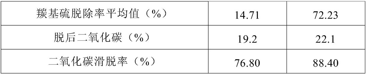
[0076] Composite desulfurizer used in Example 1 is compared with MDEA desulfurizer (30% MDEA aqueous solution) in the laboratory evaluation device for performance comparison, see Table 4 for specific comparison results.

[0077] Table 4

[0078]

[0079]

[0080] Note: The data in Table 4 are all measured under static absorption test conditions.

[0081] The comparison results in Table 4 show that the hydrogen sulfide removal effect of the composite desulfurizer is similar to that of the MDEA desulfurizer, but the removal rate of COS is 4.9 times that of the MDEA desulfurizer; With large sulfur capacity, the carbon dioxide slip rate is 11.6 percentage points higher than that of MDEA desulfurizer.

Embodiment 2

[0083] This embodiment provides a deep desulfurization method for sulfur-containing gas, wherein the sulfur-containing gas comes from the product of sulfur tail gas desulfurized by the SCOT process. The specific process of SCOT process desulfurization is carried out according to the above steps 1 to 5, and the specific process of deep desulfurization is carried out according to the above steps 6 to 8.

[0084] See Table 5 for specific process parameters of SCOT process desulfurization and deep desulfurization. Wherein, the component weight percent of the composite desulfurizer used in step 6 is: sulfolane: 20%, DIPA: 20%, N-methylpyrrolidone: 40%, 1,2-butanediol: 10%, water: 10% .

[0085] The components of the sulfur hydrogenation tail gas obtained in step 2, the sulfur-containing gas obtained in step 5, and the desulfurized gas obtained by deep desulfurization of the sulfur-containing gas are shown in Table 6.

[0086] table 5

[0087]

[0088]

[0089] Table 6

[...


PUM


Abstract

The invention provides a compound desulfurizer and a sulfurous gas deep desulfurization method, wherein the compound desulfurizer comprises 2-40 parts of sulphone or sulfoxide, 2-30 parts of organic amine desulfurizer, 0-20 parts of C3-C8 monohydric alcohol or dihydric alcohol, and 5-90 parts of an enhancer, wherein the enhancer is chosen from at least one of N-formyl morpholine, N-methylpyrrolidone, polyethylene glycol, triethylene glycol, tetraglycol and propylene carbonate. The provided compound desulfurizer achieves simultaneous deep desulfurization of hydrogen sulfide and an organic sulfur ingredient in the sulfurous gas, and the sulfurous gas deep desulfurization method adopting the compound desulfurizer also has the advantages of low cost for equipment transformation and low operation energy consumption.

Description

technical field [0001] The invention relates to deep desulfurization technology of sulfur-containing gas, in particular to a compound desulfurizer capable of simultaneously deep removal of hydrogen sulfide and organic sulfur components in sulfur tail gas and a method for deep desulfurization of sulfur-containing gas. Background technique [0002] The treatment effect of sulfur-containing tail gas has always been an important factor affecting the quality of exhaust gas. The usual practice is to desulfurize the sulfur-containing tail gas until the sulfur content is low to a certain extent, and then discharge it at high altitude in the form of sulfur-containing oxides through incineration. . Sulfur-containing tail gas refers to the sulfur-containing gas discharged from various processing units. The composition of the tail gas will be different due to different sources. The sulfur will be in the form of elemental sulfur, sulfide and organic sulfur (such as COS, CS 2 etc.), so t...

Claims


Application Information

Patent Timeline
IPC IPC(8): B01D53/14
CPCB01D53/1468B01D53/1487B01D53/1493B01D2252/504B01D2257/308
Inventor 郝天臻李德忠白春栋王桂花何晓明
Owner 郝天臻
Why Eureka
Try Eureka