Laser water jet processing device and application thereof

A processing device and water jet technology, which is applied in the field of laser processing and laser water jet processing devices, can solve problems such as low efficiency, small heat-affected zone, and long processing time, and achieve the effects of reducing costs, realizing industrialization, and efficient cutting

Active Publication Date: 2018-07-20
TIANJIN UNIV OF SCI & TECH
View PDF6 Cites 12 Cited by
  • Summary
  • Abstract
  • Description
  • Claims
  • Application Information

AI Technical Summary

Problems solved by technology

The advantages are ① high material utilization rate: the minimum slit width can reach 0.1mm, generally in the range of 0.1-0.3mm; ② small heat-affected zone: generally in the range of 0.1-0.15mm, the workpiece deformation is small; ③ The quality of the cutting section is good ; ④ fast cutting speed and high efficiency; ⑤ no tool wear and compensation problems, but there are still some defects in laser cutting PCBN, such as the formation of recasting layer, the incision requires secondary grinding, and the material removal rate is low, melting The material cannot be cooled in time and adheres to the PCBN material again, resulting in long processing time, high energy consumption, and low efficiency.
[0006] The current laser cutting method is pulse laser cutting, but it is easy to form a recast layer, and the incision needs to be grinded twice. The hardness and brittleness of ceramics lead to low material removal rate and slow speed, high energy consumption, and the melted material cannot be processed in time. Cool to adhere to the PCBN material again

Method used


Image

  • Laser water jet processing device and application thereof
  • Laser water jet processing device and application thereof
  • Laser water jet processing device and application thereof

Examples


Embodiment Construction

[0026] The present invention will be further described in detail below in conjunction with the accompanying drawings and through specific embodiments. The following embodiments are only descriptive, not restrictive, and cannot limit the protection scope of the present invention.

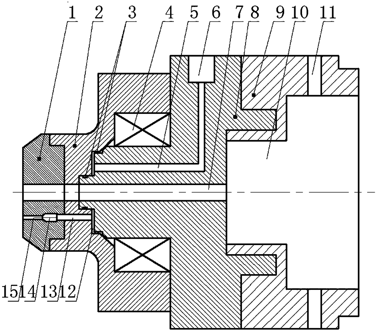
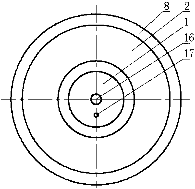
[0027] A laser water jet processing device, including a laser emitting device and a laser head connected to it, the laser head includes a nozzle 1, a rotating disk 2, a separation base 8 and a connecting seat 9 connected coaxially in sequence, and the nozzle, rotation The center of the disk and the separation base is coaxially connected with a laser through hole 7, which communicates with the laser through hole 10 of the connecting seat. Nozzle 14 is shaped on the second water flow channel 13 communicated with the first water flow channel in the rotating disk, the gap between the rotating disk and the separation base forms the third water flow channel 12, and two water flow channels are installed on b...


PUM

PropertyMeasurementUnit
lengthaaaaaaaaaa
laser poweraaaaaaaaaa

Abstract

The invention relates to a laser water jet processing device and application thereof. The processing device comprises a laser emitting device and a laser head connected to the laser emitting device. The laser head comprises a spray-head, a rotating disc, a separation pedestal and a connecting seat which are successively and coaxially connected. A laser through hole is formed in the center of the spray-head, the center of the rotating disc and the center of the separation pedestal in a coaxial communication mode. The laser through hole communicates with a laser penetrating hole of the connecting seat. A first water flow passage is formed in the spray-head. A water spray head is installed in the first water flow passage. A second water flow passage is formed in the rotating disc. A third water flow passage is formed in a gap between the rotating disc and the separation pedestal. A fourth water flow passage is formed in the separation pedestal. A water inlet is formed in the outer wall ofthe separation pedestal. Multiple auxiliary gas inlets are formed in the connecting seat. More efficient cutting can be realized, materials can be quickly cooled down by a water jet in the cutting process, and a high-precision device is not necessary for the water jet. Cost of the device is greatly reduced, and industrialization is favorable for realizing.

Description

technical field [0001] The invention belongs to the field of hard and brittle material processing, and relates to laser processing, in particular to a laser water jet processing device and its application. Background technique [0002] Polycrystalline cubic boron nitride (PCBN) is a new type of material composed of many small cubic boron nitride (CBN) single crystals through a binder under high temperature and pressure. It is another new type of superhard material after artificial diamond. synthetic material. It has excellent characteristics such as high hardness and wear resistance, thermal stability and chemical inertness, low friction coefficient and good thermal conductivity. Therefore, it is widely used in the cutting tool industry, and its appearance has opened up broad prospects for the cutting of ferrous metals and hard, tough and difficult-to-machine materials. Although diamond is the hardest material, diamond tools also have limitations, because its chemical prop...

Claims


Application Information

Patent Timeline
Patent Type & Authority Applications(China)
IPC IPC(8): B23K26/14B23K26/146B23K26/402
CPCB23K26/14B23K26/146B23K26/402
Inventor 赵静楠司学康郭健马晓磊
Owner TIANJIN UNIV OF SCI & TECH
Why Eureka
Try Eureka