Calibration device and method for acoustic wave scattering region of Doppler current meter

A technology of Doppler current and scattering area, applied in the field of acoustic measurement, can solve the problems of large effective acoustic scattering area, small effective acoustic scattering area, limited sensitivity of hydrophone, etc., so as to improve reliability and reduce stagnation point pressure. , the effect of high signal-to-noise ratio

Active Publication Date: 2018-07-20
HARBIN ENG UNIV
View PDF5 Cites 8 Cited by
  • Summary
  • Abstract
  • Description
  • Claims
  • Application Information

AI Technical Summary

Problems solved by technology

However, when using Doppler ocean current timing, a transducer is required to emit sound waves and a transducer to receive sound waves. When the transducer is powered on, it will produce nonlinear effects. At this time, the reciprocity of sending and receiving is no longer satisfied. Therefore, , there are certain problems in calibrating the intersection area of ​​the transducer with the acoustic flow imaging method
[0007] In addition, there is a method of using a needle hydrophone to calibrate the effective acoustic scattering area of ​​the Doppler current meter. This method is limited by the sensitivity of the hydrophone. When a hydrophone with higher sensitivity is used to complete the calibration, It will make the effective acoustic scattering area too large; when the hydrophone with lower sensitivity is used to complete the calibration, the effective acoustic scattering area will be too small; moreover, the hydrophone has a certain volume and size, when the local structure feels the sound wave When the pulsating pressure is high, there will also be an electrical signal output, which is one of the reasons for the error in the calibration area

Method used


Image

  • Calibration device and method for acoustic wave scattering region of Doppler current meter
  • Calibration device and method for acoustic wave scattering region of Doppler current meter
  • Calibration device and method for acoustic wave scattering region of Doppler current meter

Examples


Embodiment Construction

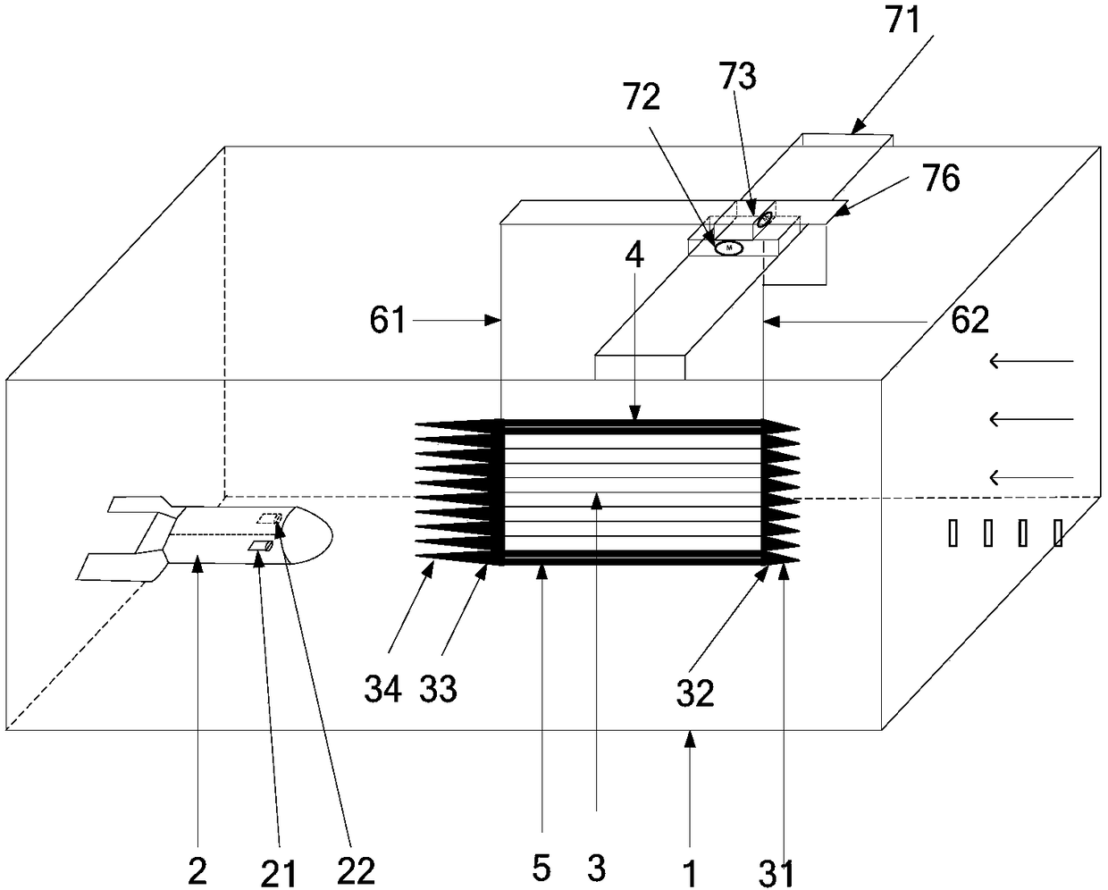
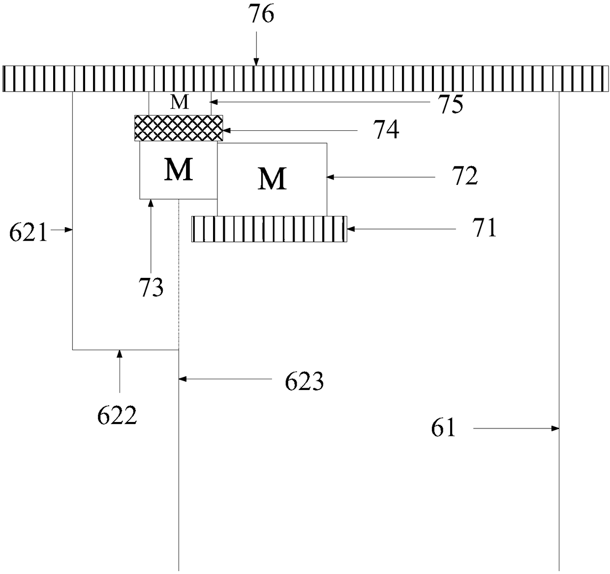
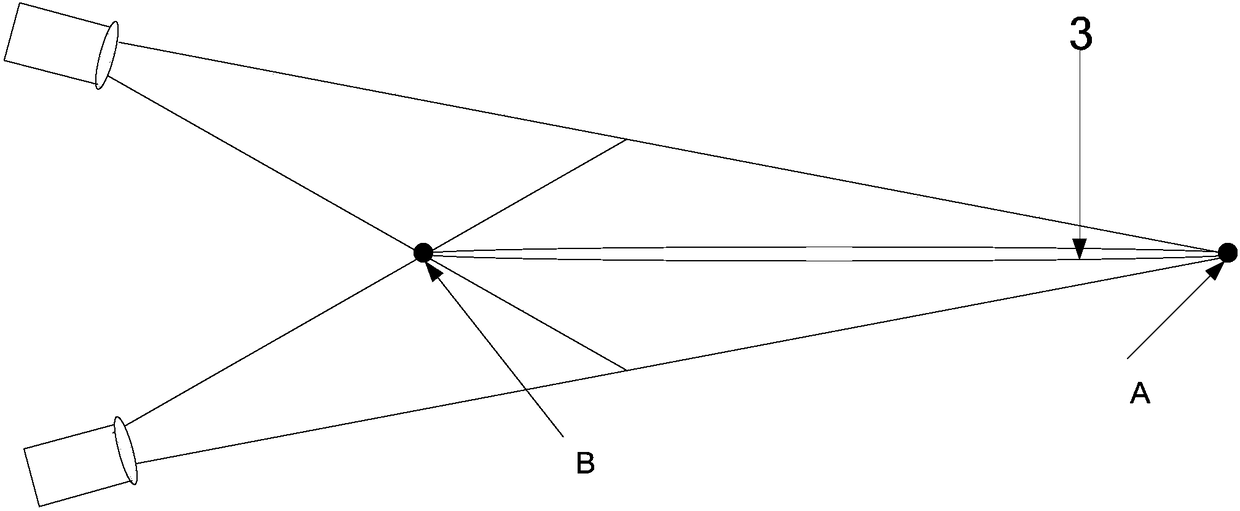
[0048] Attached below Figure 1-5 , the device and method for calibrating the acoustic wave scattering area of ​​a Doppler current meter according to the present invention will be further described.

[0049] Such as figure 1 , figure 2 As shown, 1 is the working section of the circulating water tank, 2 is the Doppler current meter, 21 is the transmitting transducer, 22 is the receiving transducer, 3 is the standard plate, 31 is the short cone, 32 is the first thin stud , 33 is the second thin stud, 34 is the long cone, 4 is the upper shock absorber, 5 is the lower shock absorber, 61 is the first connecting rod, 62 is the second connecting rod, 621 is the upper vertical rod, 622 It is a horizontal bar, 623 is a lower vertical bar, 71 is a first guide rail, 72 is a first linear stepper motor, 73 is a rotary stepper motor, 74 is a turntable, 75 is a second linear stepper motor, and 76 is a second linear stepper motor. Two guide rails, the arrow represents the water flow direc...


PUM


Abstract

The invention relates to a calibration device and method for a sound wave scattering region of a Doppler current meter. The device comprises a standard plate (3), an upper damper (4), a lower damper (5), a first connecting rod (61), a second connecting rod (62) and a moving mechanism. The standard plate (3) is formed by connecting the round tubes to each other. One end of each of the round tubes is provided with a long cone (34), and the other end is provided with a short cone (31). The moving mechanism includes a first guide rail (71), a first linear stepping motor (72), a rotary stepping motor (73), a turntable (74), a second linear stepping motor (75) and a second guide rail (76). The first connecting rod (61) is a straight rod, the second connecting rod (62) includes an upper verticalrod (621), a horizontal rod (622) and a lower vertical rod (623), and the axis of the lower vertical rod (623) and the rotation axis of the rotary stepping motor (73) are in the same straight line. The effective acoustic scattering region of the Doppler current meter can be accurately calibrated.

Description

technical field [0001] The invention relates to a calibration device and method, in particular to a calibration device and method for the acoustic wave scattering area of ​​a Doppler current meter, belonging to the field of acoustic measurement. Background technique [0002] The Doppler current meter uses the Doppler effect generated by sound waves in the moving medium to measure flow velocity. The traditional Doppler current meter uses a transducer at the front end to emit sound waves. The sound waves are scattered by moving media such as water flow, small particles, and bubbles. The scattered sound waves are received by another transducer. According to the Doppler frequency deviation generated by moving objects , to calculate the flow rate of the water. In the past, the speed measurement accuracy of the calibration sea current meter was mostly carried out in the field waters. The Chinese marine industry standard HY / T102-2007 (the detection method of the acoustic Doppler c...

Claims


Application Information

Patent Timeline
Patent Type & Authority Applications(China)
IPC IPC(8): G01P21/02
CPCG01P21/025
Inventor 刘永伟姜虹旭裴杰商德江
Owner HARBIN ENG UNIV
Why Eureka
Try Eureka