
Near-field acoustic tomography test method for mutual radiation impedance of underwater acoustic array

A technology of mutual radiation impedance and testing method, applied in the field of basic research of underwater acoustic technology, to achieve the effect of improving electro-acoustic efficiency, improving efficiency and eliminating negative effects

Inactive Publication Date: 2018-07-24
THE 715TH RES INST OF CHINA SHIPBUILDING IND CORP
View PDF5 Cites 5 Cited by
  • Summary
  • Abstract
  • Description
  • Claims
  • Application Information

AI Technical Summary

Problems solved by technology

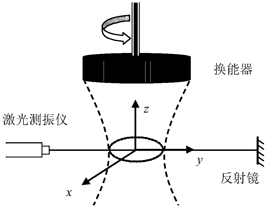
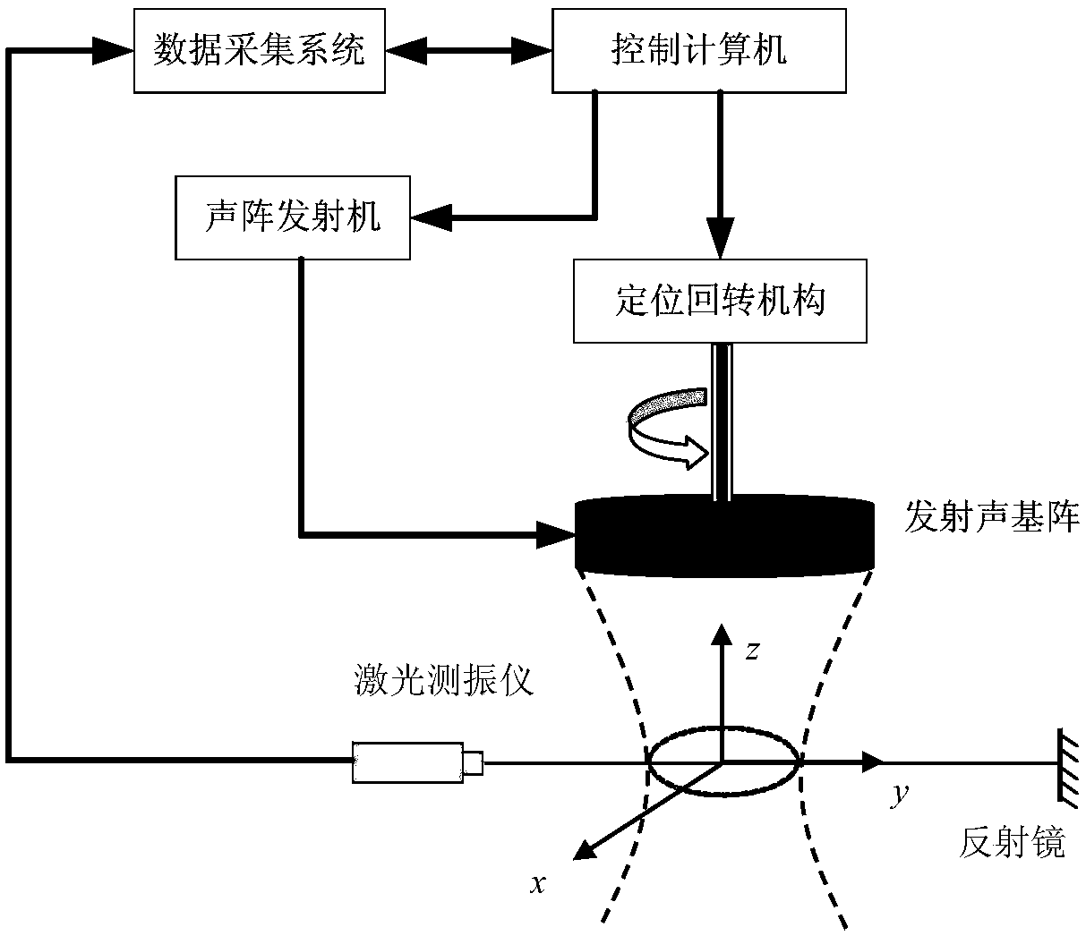
[0004] The purpose of the present invention overcomes the deficiencies of the existing interventional underwater acoustic-based array radiation impedance testing method, especially solves the method and accurate measurement problem required for the array element mutual radiation impedance test under the high-power operation of the low-frequency active sonar array, and provides A near-field acoustic tomography test method for the mutual radiation impedance of underwater acoustic arrays, mainly using a non-contact underwater acoustic array mutual radiation impedance test method

Method used


Image

  • Near-field acoustic tomography test method for mutual radiation impedance of underwater acoustic array
  • Near-field acoustic tomography test method for mutual radiation impedance of underwater acoustic array
  • Near-field acoustic tomography test method for mutual radiation impedance of underwater acoustic array

Examples


Embodiment Construction

[0017] The present invention will be described in detail below in conjunction with accompanying drawing:

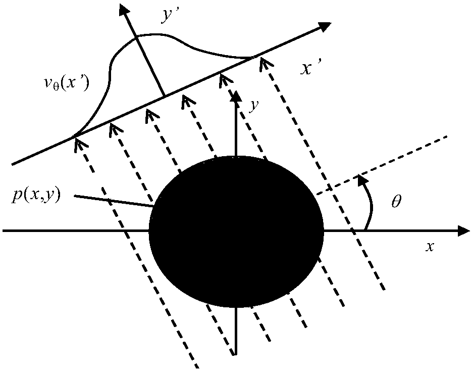
[0018] Due to the influence of size, underwater acoustic arrays usually adopt dense arrays. Especially when working at low frequencies, since the distance between the array elements does not meet the 1 / 4 wavelength, there is an influence of mutual radiation between the array elements. This effect will reduce the working efficiency of the base array, and will damage the base array in severe cases. Usually, the intervening mutual radiation test method can be used to test at low frequency and low power. But most of the modern new sonars work at low frequency and high power. The existing intrusive test system will destroy the test equipment under any high power, and bring errors to the measured acoustic array. The non-invasive near-field acoustic tomography test method is used to test the mutual radiation impedance of the underwater acoustic array. We use optical tomograph...


PUM


Abstract

The invention belongs to the field of underwater acoustic test technology base, and mainly relates to a near-field acoustic tomography measurement method for the mutual radiation impedance of an underwater acoustic array. The method includes the following steps: obtaining near-field acoustic field information of a radiated acoustic field of an acoustic array through laser tomography measurement; processing the obtained acoustic field information by using a near-field acoustic holographic transformation technology; dividing the complex vibration velocity into blocks according to the position ofeach array element to obtain the complex vibration velocity of the source surface of each array element; calculating the complex acoustic pressure of the source surface of each array element and theradiated acoustic pressure generated by the array element in the surface positions of the other array elements; and carrying out calculation based on the classic acoustic array mutual radiation impedance theory. The beneficial effects are as follows: the shortcomings of the common intrusive acoustic array mutual radiation test method are overcome by a non-contact test method; the problem that there is no method for accurately testing the mutual radiation impedance of an underwater acoustic array at low frequency and high power is solved; a mutual radiation model is provided for the velocity control of an underwater acoustic array; and a powerful technical guarantee is provided for the design and development of a low-frequency and high-power acoustic array.

Description

technical field [0001] The invention relates to the field of basic research of underwater acoustic technology, belongs to the underwater acoustic array radiation impedance testing technology, and mainly relates to a near-field acoustic tomography test method for the underwater acoustic array mutual radiation impedance. Background technique [0002] With the development of underwater acoustic technology, the application frequency of underwater acoustics gradually expands to low frequencies. In order to increase the long-range detection and early warning capabilities of underwater targets, it is especially necessary to solve the problem of effective detection of low-noise targets. Active sonar arrays are gradually developing in the direction of low frequency, large aperture, and high power. In order to achieve high enough transmission power in a limited space, the array elements are usually arranged in a dense array in the design of active sonar arrays. When the distance betw...

Claims


Application Information

Patent Timeline
Patent Type & Authority Applications(China)
IPC IPC(8): G01H9/00
CPCG01H9/00G01H9/002
Inventor 平自红纪京召王世全王少博贾广慧
Owner THE 715TH RES INST OF CHINA SHIPBUILDING IND CORP
Learn More