
Fabrication method of curved microlens array with focal length varying with spatial distribution

A technology of microlens array and spatial distribution, which is applied in the production field of curved surface microlens array, can solve the problems of high production cost, expensive rotatable and movable laser emission source, unsuitable for mass production, etc., and achieve low cost and optimal control , the effect of simple steps

Active Publication Date: 2019-08-30
UNIV OF SHANGHAI FOR SCI & TECH
View PDF2 Cites 0 Cited by
  • Summary
  • Abstract
  • Description
  • Claims
  • Application Information

AI Technical Summary

Problems solved by technology

[0005] 1. The curved surface microlens array is produced point by point on the curved surface substrate, and the curved surface microlens array is produced by laser photolithography directly on the spherical surface. This method can produce a relatively perfect curved surface microlens array. However, this method requires a relatively precise and expensive rotatable and movable laser emission source, so the production cost is very high, and it is not suitable for mass production

Method used


Image

  • Fabrication method of curved microlens array with focal length varying with spatial distribution
  • Fabrication method of curved microlens array with focal length varying with spatial distribution
  • Fabrication method of curved microlens array with focal length varying with spatial distribution

Examples


Embodiment Construction

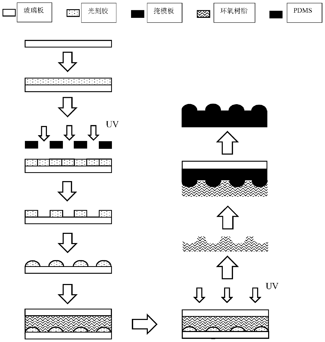
[0025] The invention discloses a manufacturing method of a curved surface microlens array whose focal length varies with spatial distribution, such as figure 1 As shown, the following process steps are included:

[0026] 1. Take a glass sheet with a flat surface as the substrate, wash the glass sheet with water and acetone, place it in an oven, and bake it at 130°C for 10 minutes to remove water vapor and residual acetone. After baking, perform oxygen plasma treatment. Increase the surface energy of the glass sheet.

[0027] 2. Spin-coat the positive photoresist (AZ4620) on the cleaned substrate. After pre-baking, a uniform adhesive layer is formed on one side of the substrate. Place the adhesive layer side of the substrate under the pre-made circular hole mask for UV exposure. , the substrate is spaced but parallel to the circular hole mask, and the ultraviolet light is irradiated vertically on the circular hole mask. The circular hole mask includes a light-transmitting area...


PUM


Abstract

The invention relates to a manufacturing method of a curved micro-lens array of which the focal length varies with spatial distribution. A planar micro-lens array PDMS film is prepared on the preparedmother board, then a PDMS film varying along the radial thickness is manufactured, then a layer of PDMS is poured, the planar micro-lens array film is put on the PDMS, and then the rotationally symmetrical and radial thickness varying planar micro-lens array is manufactured after curing; and the planar micro-lens array is fixed on a closed clamp, the curved micro-lens array can be manufactured bychanging the internal and external pressure intensity difference, and all the small lenses are identical in curvature, diameter and spacing angle and different in radial film thickness so as to formthe curved micro-lens array of which the focal length varies with the spatial distribution. The method is simple in structure without complex equipment and low in cost. Compared with the planar micro-lens array, the curved micro-lens array has the characteristic of wide viewing angle possessed by the insect compound eyes, and the light condensing range of the curved micro-lens array can be changedby changing the bending degree of the micro-lens array through the pressure intensity difference.

Description

technical field [0001] The invention relates to a manufacturing technology of an optical instrument, in particular to a manufacturing method of a curved microlens array whose focal length varies with spatial distribution. Background technique [0002] With the continuous development of science and technology, optical imaging systems are widely used in every field, such as applications in guidance systems, applications in remote sensing imaging, applications in infrared night vision devices, applications in medical equipment, etc., so People's requirements for it are also constantly increasing, hoping that it will develop in the direction of smaller volume, lighter weight, and larger field of view. Therefore, bionic compound eyes have become a frontier topic of research. [0003] In nature, biological compound eyes are composed of a group of "small eyes" gathered together, and usually the entire compound eye has a curved structure. The entire field of view can be divided in...

Claims


Application Information

Patent Timeline
Patent Type & Authority Patents(China)
IPC IPC(8): G02B3/00
Inventor 盛斌王冬黄元申彭丽娜史俊王良玉张翔陈惠康刘安琦
Owner UNIV OF SHANGHAI FOR SCI & TECH
Learn More