Electrical current control device and electrical current control method
A technology of current control and power supply device, applied in circuits, electrical components, pulse duration/width modulation, etc., can solve problems such as inability to process, and achieve good lighting effects
- Summary
- Abstract
- Description
- Claims
- Application Information
AI Technical Summary
Problems solved by technology
Method used
Image

Examples
Embodiment approach 1
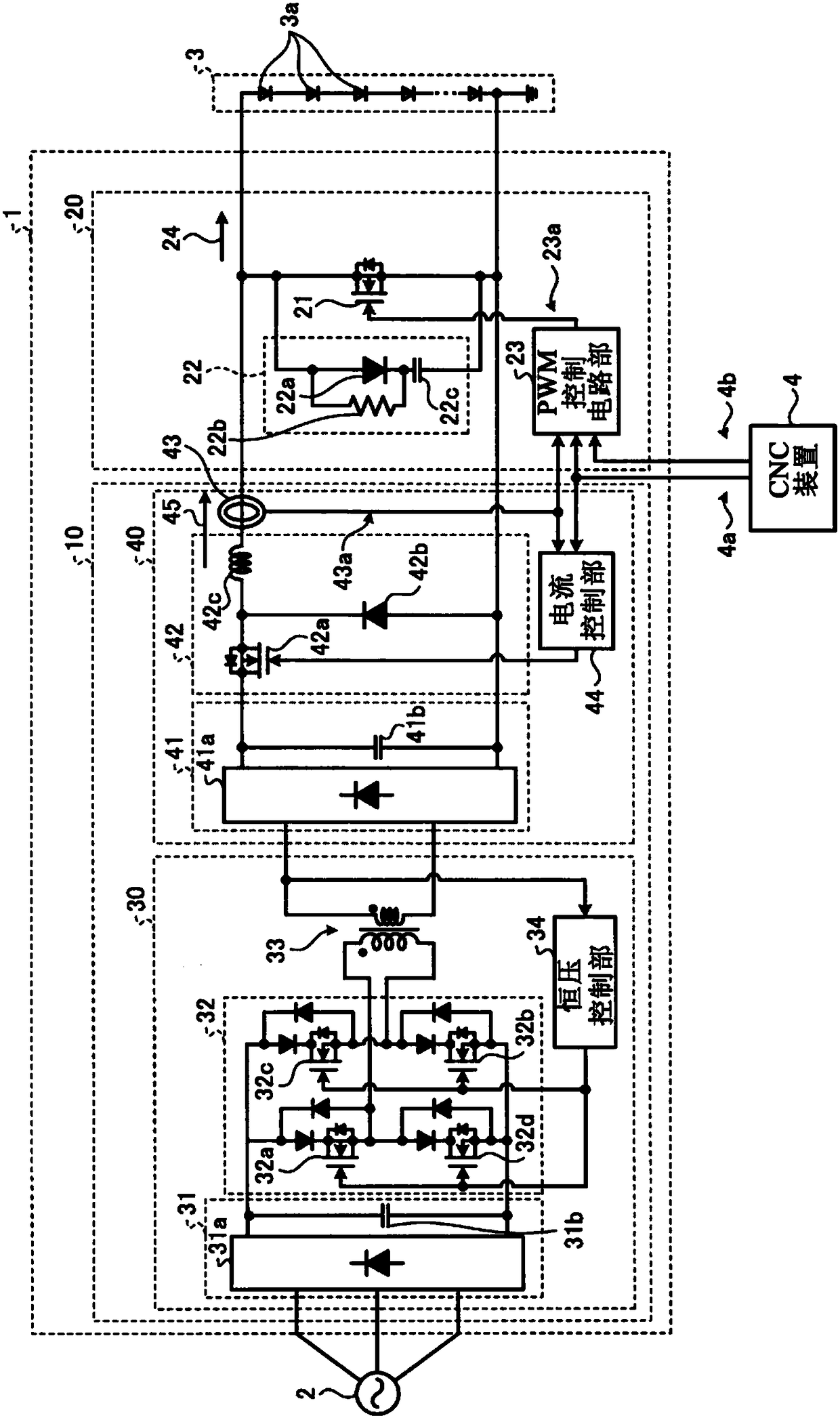
[0040] figure 1 It is a diagram showing the configuration of a laser diode power supply device including the current control device according to the first embodiment.
[0041] The laser diode power supply device 1 receives a three-phase AC power supply from a system power supply 2 , and flows a current corresponding to a current command value 4 a input from an external computer numerical control (CNC) device 4 to the light emitting unit 3 .
[0042] The light emitting unit 3 includes one or more laser diodes (Laser Diode: LD) 3a. When the light emitting unit 3 includes a plurality of laser diodes 3a, the plurality of laser diodes 3a are connected in series, in parallel, or in series and parallel.
[0043] The laser diode 3a is a current-driven element, and emits light with an intensity corresponding to the current. Therefore, the laser diode power supply device 1 can control the intensity of the light of the light emitting unit 3 by controlling the current flowing in the lig...
Embodiment approach 2
[0146] Figure 12 It is a diagram showing the configuration of a laser diode power supply device including the current control device according to the second embodiment. If the laser diode power supply device 130 according to Embodiment 2 is connected with the figure 1 For comparison, the laser diode power supply device 1 according to Embodiment 1 shown includes a power supply device 140 instead of the power supply device 10 .
[0147] The power supply device 10 shown in Embodiment 1 includes a step-down chopper unit 42 that steps down the DC voltage supplied from the DC conversion unit 41 .
[0148] The power supply device 140 shown in Embodiment 2 omits the step-down chopper unit 42 . When the laser output of the light emitting unit 3 is allowed to be small and the power supply capacity is small, the step-down chopper unit 42 can be omitted.
[0149] The power supply unit 140 includes: a transformer 141 that transforms the AC voltage supplied from the inverter unit 32 to ...
Embodiment approach 3
[0156] The structure of the laser diode power supply device including the current control device according to Embodiment 3, and the figure 1 The laser diode power supply device 1 according to Embodiment 1 shown may be composed of Figure 12 The laser diode power supply device 130 according to the illustrated second embodiment is the same, and thus illustration and description thereof will be omitted.
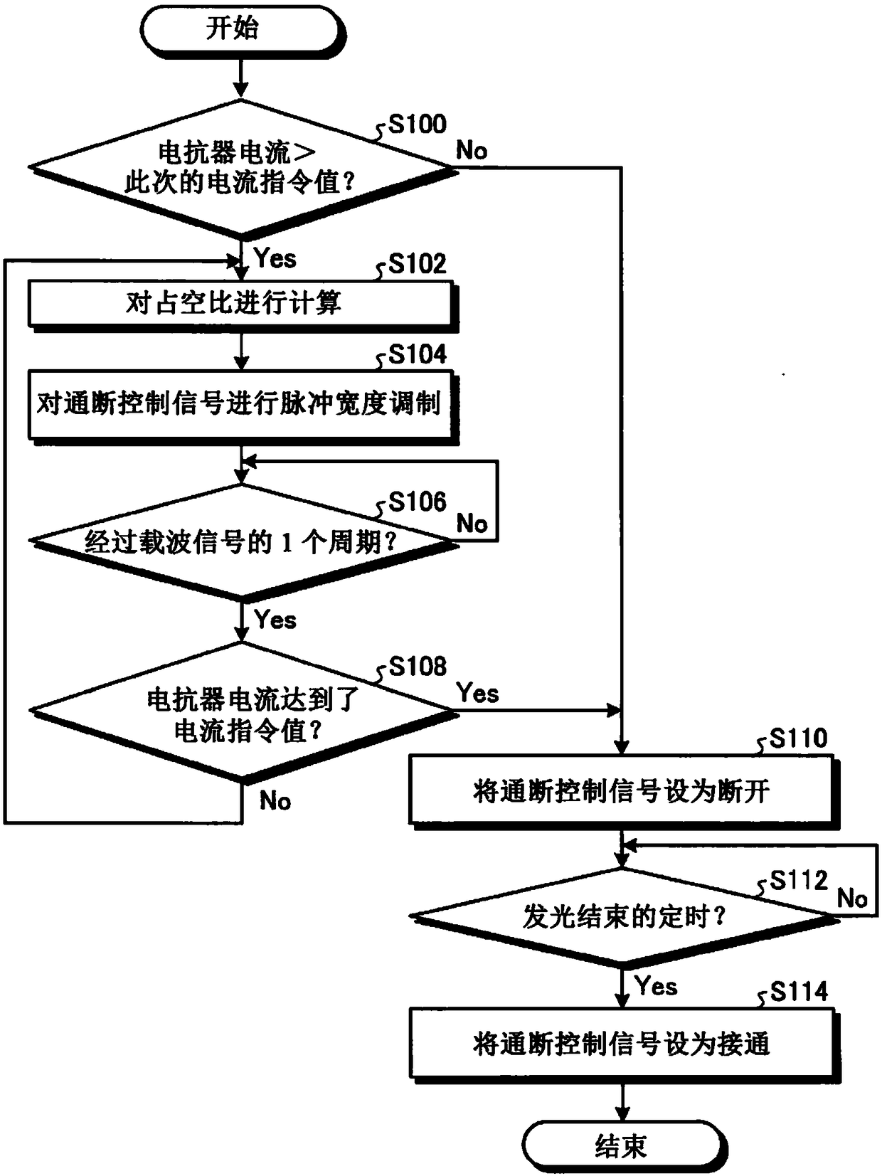
[0157] Figure 13 It is a flowchart showing the operation of the current control device according to Embodiment 3. Figure 14 It is a waveform diagram for explaining the operation of the current control device according to the third embodiment. exist Figure 14 In , the waveform of the current command value 4a, the waveform of the on-off control signal 23a, the waveform of the reactor current 45, and the waveform of the light emitting unit current 24 are shown.
[0158] If the timing t of the start of light emission indicated by the first light emission timing signal is reac...
PUM
 Abstract
Description
Claims
Application Information
 - R&D
- Intellectual Property
- Life Sciences
- Materials
- Tech Scout
- Unparalleled Data Quality
- Higher Quality Content
- 60% Fewer Hallucinations
Browse by: Latest US Patents, China's latest patents, Technical Efficacy Thesaurus, Application Domain, Technology Topic, Popular Technical Reports.
© 2025 PatSnap. All rights reserved.Legal|Privacy policy|Modern Slavery Act Transparency Statement|Sitemap|About US| Contact US: help@patsnap.com