Particulate matter detection device and detection method

A particle and detection technology, which is applied in the field of electrical impedance measurement microfluidic chips, can solve the problems of difficult to distinguish different particles, increase steps and costs, and achieve the effects of low detection cost, easy operation and good industrial application prospects.

Active Publication Date: 2018-08-10
上海欣戈赛生物科技有限公司
View PDF9 Cites 9 Cited by
  • Summary
  • Abstract
  • Description
  • Claims
  • Application Information

AI Technical Summary

Problems solved by technology

However, in the actual detection of samples (such as blood), due to the size of target particles (such as circulating tumor cells, CTCs) and non-target particles such as blood cells (especially white blood cells such as macrophages and monocytes), the resulting electrical impedance The signals are quite close, and it is difficult to distinguish different particles based on the electrical impedance signal
Therefore, it is usually necessary to perform fluorescent staining on target particles such as cells or use additional cell labeling methods such as detection antibodies to be able to distinguish target particles, but at the same time additional steps and costs are added. Labeled electrical impedance detection technology capable of distinguishing different types of particles

Method used


Image

  • Particulate matter detection device and detection method
  • Particulate matter detection device and detection method
  • Particulate matter detection device and detection method

Examples


Embodiment 1

[0067] Embodiment 1 Preparation of microfluidic chip

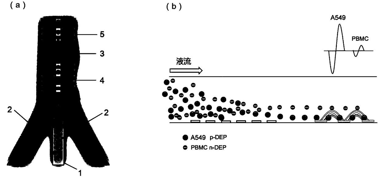
[0068] Using conventional methods in the art to prepare such as figure 1 The microfluidic chip shown, which includes the sample channel (1) in the middle and the sheath liquid channel (2) on both sides, the three channels merge at the outlet to form the main channel (3), the dielectrophoresis generating electrode (4) and the resistor The anti-detection electrodes (5) are all located below the main channel (3). The dielectrophoresis generating electrode (4) is externally connected to the electrical signal generating device, and the electrical impedance detection electrode (5) is connected to the electrical signal generating device and the electrical signal receiving and analyzing device.

Embodiment 2

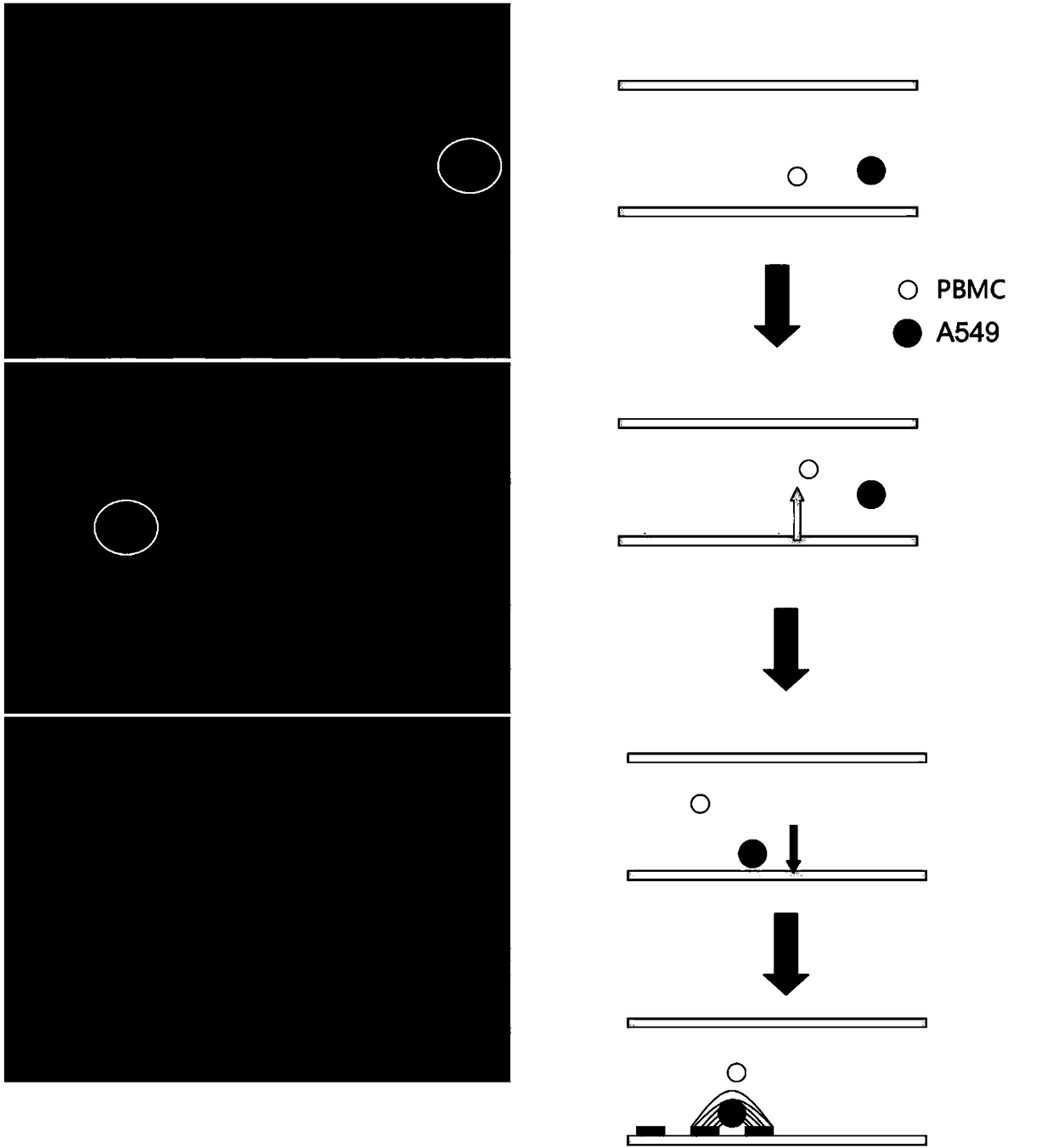
[0069] Example 2 Dielectrophoresis Cell Stratification Effectively Differentiates A549 Lung Adenocarcinoma Cells and PBMC Cells

[0070] Construction of A549 cell line with GFP marker

[0071] Initial cell line: A549 human non-small cell lung cancer cell line was purchased from ATCC. The original source of this cell line was a 58-year-old white male lung cancer patient, established by D.J.Gard et al. in 1972.

[0072] DNA expression vector: pLEIN vector, which contains a bicistronic expression of EGFP and neomycin resistance genes, and also contains an internal ribosome entry site (IRES),

[0073] Cell culture, vector production, transfection and subcloning: NIH3T3-derived packaging cell line PT67 expressing 10AI viral envelope was purchased from Clontech Laboratories, Inc. PT67 cells were cultured in DMEM supplemented with 10% heat-inactivated fetal calf serum (Gemini Bio-products, Calabasas, CA). For vector production, a 70% confluent packaging cell line (PT67) was incubat...

Embodiment 3

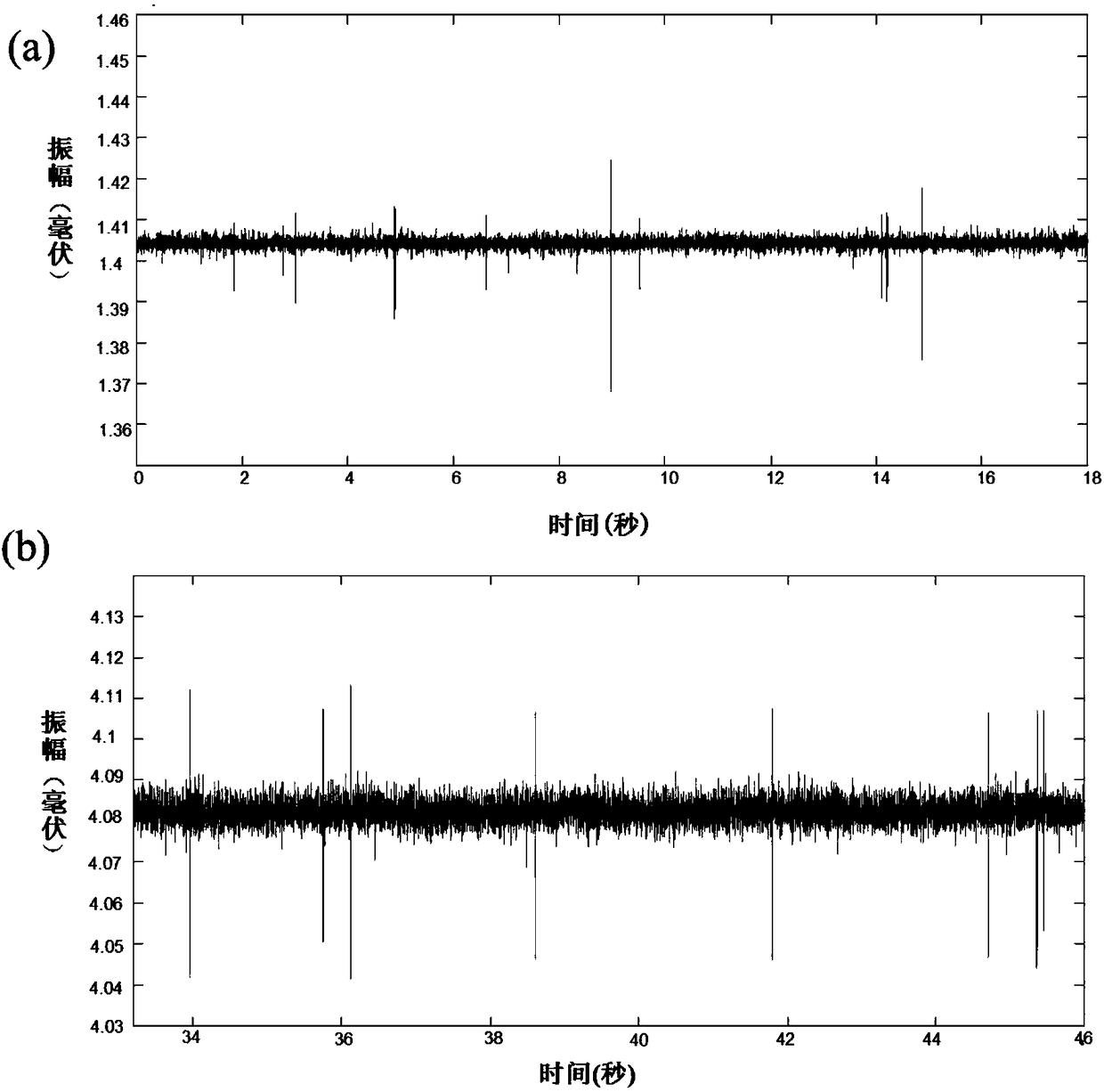
[0086] Example 3 Dielectrophoretic focusing improves the stability of the target signal


PUM

PropertyMeasurementUnit
electrical conductivityaaaaaaaaaa

Abstract

The invention relates to a particulate matter detection device and a detection method, in particular relates to a detection device and a detection method based on a dielectrophoresis and electrical impedance measurement technology, and more in particular relates to an electrical impedance detection device utilizing a microfluidic chip and application of the electrical impedance detection device todetection of target particles.

Description

technical field [0001] The invention relates to a device and method for detecting particulate matter by using dielectrophoresis and electrical impedance measurement, in particular to a microfluidic chip for measuring electrical impedance enhanced by dielectrophoresis and a detection method using the chip. Background technique [0002] Most electrical impedance measurement technologies use microfluidic chips or electric field focusing to make particles appear as a single particle flow and pass through the measurement electrodes, and then detect and count particles based on the obstruction and resistance of particles to the measured voltage or current. However, in the actual detection of samples (such as blood), due to the size of target particles (such as circulating tumor cells, CTCs) and non-target particles such as blood cells (especially white blood cells such as macrophages and monocytes), the resulting electrical impedance The signals are quite close, and it is difficul...

Claims


Application Information

Patent Timeline
Patent Type & Authority Applications(China)
IPC IPC(8): G01N15/00G01N15/10
CPCG01N15/0656G01N2015/1006G01N15/1056G01N15/1031B01L3/502761B01L2200/0652B01L3/502776B01L2400/0424B01L2300/0645B03C5/005B03C5/026B03C2201/26B01L2300/0816G01N2015/149
Inventor 李珍仪陈昭宏姜竣凯王竣弘陆祎
Owner 上海欣戈赛生物科技有限公司
Why Eureka
Try Eureka