Triboelectric nanogenerators, micromechanical sensors and sensing systems

A nanogenerator and sensor technology, applied in the field of sensors, can solve the problems of inability to accurately calculate the propagation speed of pulse waves, easy leakage of charges, inability to test surface fit, etc., to achieve wireless transmission and visual analysis, and improve sensitivity and noise. Compare and realize the effect of non-invasive monitoring technology

Active Publication Date: 2019-11-15
BEIJING INST OF NANOENERGY & NANOSYST
View PDF9 Cites 1 Cited by
  • Summary
  • Abstract
  • Description
  • Claims
  • Application Information

AI Technical Summary

Problems solved by technology

The piezoresistive type has high sensitivity and good response frequency, but the sex-to-noise ratio is not high, the structure is complex, and it is greatly affected by temperature
Piezoelectric is based on the piezoelectric effect of some crystal materials, but the signal of this sensor is very weak and the output impedance is very high. It is necessary to amplify the weak signal through voltage or charge amplification, and at the same time convert the high output impedance into a low output impedance. The defect of this sensor is that the charge is easy to leak, and it is greatly disturbed by the electric field.
[0003] In addition, the micromechanical sensors currently used are composed of hard materials and media, which cannot be closely attached to the test surface, and therefore cannot be made into wearable sensors.
In addition, for conventional micro-mechanical sensors, when testing the pulse, the pulse waveforms at different positions are very different, making it difficult to compare, resulting in the inability to accurately calculate the propagation speed of the pulse wave

Method used


Image

  • Triboelectric nanogenerators, micromechanical sensors and sensing systems
  • Triboelectric nanogenerators, micromechanical sensors and sensing systems
  • Triboelectric nanogenerators, micromechanical sensors and sensing systems

Examples


Embodiment Construction

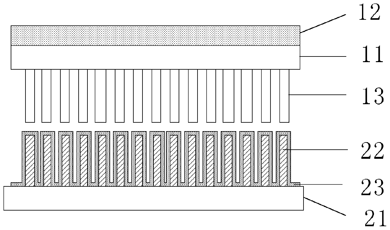
[0037] Before introducing the present invention, firstly, the design principle of the triboelectrostatic effect triboelectric nanogenerator will be described. The triboelectric nanogenerator is based on the different triboelectric properties of the surface materials of the two friction layers, and there is a difference in the ability to gain and lose electrons between the two. The friction layer material of the electrons gets electrons, so that the electrode layer attached to the two friction layer materials outputs electric signals to the outside. When the contact area between the two friction layers changes, an electrical signal will be output to the outside.

[0038] The triboelectric property of a material refers to the ability of the material to gain and lose electrons during friction or contact with other materials, that is, when two materials are in contact, one is positively charged and the other is negatively charged, indicating that the two materials gain and lose el...


PUM


Abstract

The invention provides a friction nano-generator, which comprises a first power generation layer, a second power generation layer and a packaging layer, wherein the first power generation layer comprises a first substrate material layer, a first electrode layer arranged on a first surface of the first substrate material layer and a first polymer nanostructure layer arranged on a second surface ofthe first substrate material layer; the second power generation layer comprises a second substrate material layer, a second polymer nanostructure layer arranged on a first surface of the second substrate material layer and a second electrode layer arranged on the second polymer nanostructure layer, and the second electrode layer and the first polymer nanostructure layer are arranged in a face-to-face manner; and the packaging layer is used for packaging the first power generation layer and the second power generation layer. The invention further provides a micro-mechanics sensor based on the friction nano-generator and a sensing system comprising a plurality of micro-mechanics sensors. The micro-mechanics sensor provided by the invention can detect weak mechanical signals in a real time and high precision manner, and realizes wearable applications.

Description

technical field [0001] The invention relates to a sensor, in particular to a friction nanometer generator, a micromechanical sensor and a sensing system based on the friction nanometer generator. Background technique [0002] At present, there are three main modes of micromechanical sensors: strain type, piezoresistive type and piezoelectric type. The strain gauge converts the change of force into the change of resistance value for measurement, and its resistance value changes with the strain generated by the force. This kind of sensor has low sensitivity. The piezoresistive type has high sensitivity and good response frequency, but the sex-to-noise ratio is not high, the structure is complex, and it is greatly affected by temperature. Piezoelectric is based on the piezoelectric effect of some crystal materials, but the signal of this sensor is very weak and the output impedance is very high. It is necessary to amplify the weak signal through voltage or charge amplification...

Claims


Application Information

Patent Timeline
Patent Type & Authority Patents(China)
IPC IPC(8): H02N1/04
CPCH02N1/04
Inventor 李舟田静静欧阳涵
Owner BEIJING INST OF NANOENERGY & NANOSYST
Why Eureka
Try Eureka