System and method for producing fuel chemicals by conducting solar high-temperature thermal-coupling on methane

A chemical, solar technology, applied in the field of zero carbon emission system

Inactive Publication Date: 2018-08-28
SHANGHAI ADVANCED RES INST CHINESE ACADEMY OF SCI +1
View PDF5 Cites 0 Cited by
  • Summary
  • Abstract
  • Description
  • Claims
  • Application Information

AI Technical Summary

Problems solved by technology

However, the concentrated solar energy used at high temperature drives the thermochemical reaction to decompose H 2 O / CO 2 Production H 2 and CO, while its production of O 2 As a feedstock gas coupling system for the partial oxidation of methane to produce fuel chemicals, there is no report so far

Method used


Image

  • System and method for producing fuel chemicals by conducting solar high-temperature thermal-coupling on methane
  • System and method for producing fuel chemicals by conducting solar high-temperature thermal-coupling on methane
  • System and method for producing fuel chemicals by conducting solar high-temperature thermal-coupling on methane

Examples


Embodiment example 1

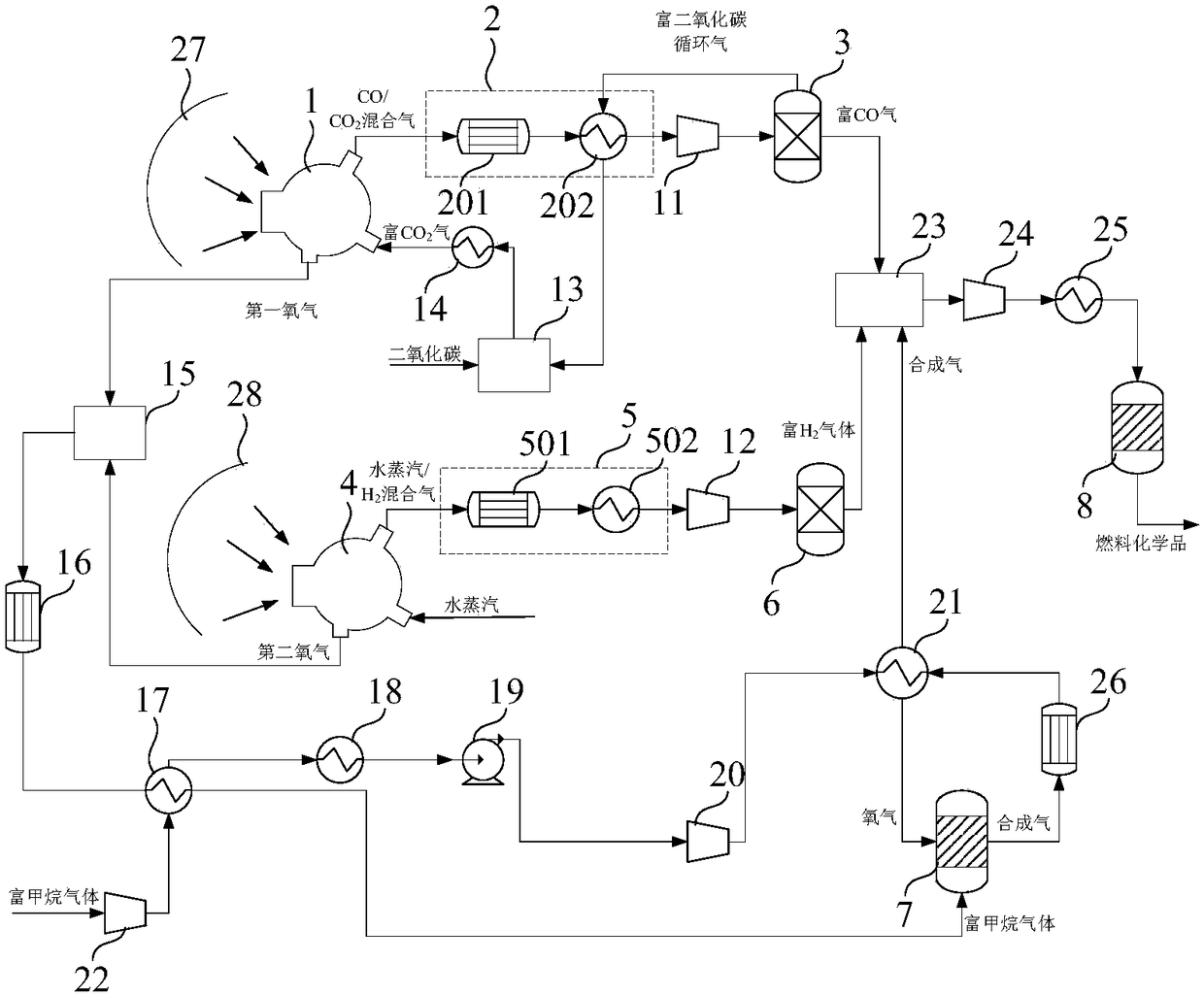
[0147] The sunlight collected from the heliostat field passes through the first CPC secondary concentrator 27, and the heat is 147381.1kW, and then enters the first high-temperature thermochemical reactor 1 through the quartz glass cover covered on the first high-temperature thermochemical reactor 1 The operating pressure in the reaction chamber is 0.2atm, the temperature in the reduction reaction zone is 1350-1400°C, and the temperature in the oxidation reaction zone is 1050-1100°C. Fresh CO required for the first high temperature thermochemical reactor 1 2 The amount is 96.4kmol / hr, the CO / CO at the outlet of the oxidation reaction zone 2 After the mixed gas is separated, the yield of CO-rich gas is 96.4kmol / hr, the molar content of CO is 84%, and the O at the outlet of the reduction zone 2 The (first oxygen) production was 41.3 kmol / hr.

[0148] The sunlight collected from the heliostat field passes through the second CPC secondary concentrator 28, and the heat is 147381....

Embodiment example 2

[0150] The sunlight collected from the heliostat field passes through the first CPC secondary concentrator 27, and the heat is 369.5MW, and enters the first high-temperature thermochemical reactor 1 through the quartz glass cover covered on the first high-temperature thermochemical reactor 1 In the reaction chamber, the operating pressure in the reaction chamber is 0.2atm, the temperature in the reduction reaction zone is 1350-1400°C, and the temperature in the oxidation reaction zone is 1050-1100°C. Fresh CO required for the first high temperature thermochemical reactor 1 2 The amount is 340.8kmol / hr, the CO / CO at the outlet of the oxidation reaction zone 2 After the mixed gas is separated, the yield of CO-rich gas is 340.8kmol / hr, the CO content is 87%, and the O at the outlet of the reduction zone 2 The (first oxygen) production was 148.2 kmol / hr.

[0151] The heat from the sunlight collected by the heliostat field is 369.5MW after passing through the second CPC secondary...


PUM


Abstract

The invention provides a system and method for producing fuel chemicals by conducting solar high-temperature thermal-coupling on methane. The method includes the steps of introducing CO2-enriched gasinto a first high-temperature thermochemical reactor, carrying out a thermochemical decomposition reaction to produce a gas mixture of CO and CO2 and first oxygen under irradiation of first sunlight,and making the gas mixture of CO and CO2 sequentially pass a first temperature reducing device and a CO2 removal device to become CO-enriched gas; introducing water vapor into a second high-temperature thermochemical reactor, carrying out a thermochemical decomposition reaction to produce a gas mixture of water vapor and H2 and second oxygen under irradiation of second sunlight, and making the gasmixture of water vapor and H2 sequentially pass a second temperature reducing device and a dewatering device to become H2-enriched gas; after mixing methane-enriched gas with the first oxygen and thesecond oxygen, carrying out a reaction in a methane partial-oxidation reactor to produce synthesis gas; mixing the synthesis gas, the CO-enriched gas and the H2-enriched gas to be introduced into a fuel chemical synthesis tower for reacting to obtain the fuel chemicals.

Description

technical field [0001] The invention relates to the technical fields of solar energy application and coal chemical industry, in particular to a zero-carbon emission system and method for producing fuel chemicals by utilizing solar high-temperature thermal coupling methane. Background technique [0002] In the face of increasingly serious energy crisis, environmental pollution and other issues, while adhering to the road of sustainable development, the resource-rich solar energy is very valuable as a new type of clean energy. It is estimated that the amount of sunlight shining on the earth is huge, and the synthesis of all the fossil energy stored on the earth is only equivalent to the sunlight shining on the earth for 18 days. The sunlight that hits the earth every hour is enough to meet the entire energy demand of the world for a year. At the same time, the sun is the ultimate source of almost all kinds of energy on the earth, directly or indirectly. Fossil fuels -- coal,...

Claims


Application Information

Patent Timeline
Patent Type & Authority Applications(China)
IPC IPC(8): C10G2/00B01J19/12C07C29/154C07C31/04
CPCB01J19/127B01J2219/0883C07C29/154C07C31/04C10G2/00Y02P20/10Y02P20/50Y02P30/40
Inventor 陈倩倩孙予罕唐志永顾宇汪丹峰
Owner SHANGHAI ADVANCED RES INST CHINESE ACADEMY OF SCI
Why Eureka
Try Eureka