

Planar anisotropic magnetoresistive film and preparation method thereof
An anisotropic magnetic and thin film technology, applied in the direction of measuring magnetic variables, ion implantation plating, coating, etc., can solve the problems of small magnetoresistance effect, small anisotropic magnetoresistance effect, simple layer structure, etc., and achieve magnetic Increased resistance effect, small temperature coefficient of magnetoresistance, avoiding low yield
- Summary
- Abstract
- Description
- Claims
- Application Information
AI Technical Summary
Problems solved by technology
Method used
Image

Examples
Embodiment 1
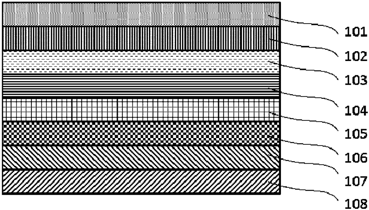
[0021] A planar anisotropic magnetoresistive film was prepared by the following method. A glass substrate is provided; a CoO layer is deposited on a glass substrate by reactive magnetron sputtering with metal Co as a target; 1-x Sr x CoO 3 As the target, magnetron sputtering was used to deposit La on the CoO layer 1-x Sr x CoO 3 layer, where x=0.1; using metal Fe as the target, using magnetron sputtering, in La 1-x Sr x CoO 3 The Fe layer is deposited on the Fe layer; the first FePt layer is deposited on the Fe layer by magnetron sputtering with FePt alloy as the target; the first FePt layer is deposited on the first FePt layer by reactive magnetron sputtering with Ni as the target NiO layer; Fe is deposited on the NiO layer by reactive magnetron sputtering using metal Fe as the target 3 o 4 layer; and using FePt alloy as target material, using magnetron sputtering, in Fe 3 o 4 A second layer of FePt is deposited on top of the layer. The thickness of the CoO layer ...
Embodiment 2
[0023] A planar anisotropic magnetoresistive film was prepared by the following method. A glass substrate is provided; a CoO layer is deposited on a glass substrate by reactive magnetron sputtering with metal Co as a target; 1-x Sr x CoO 3 As the target, magnetron sputtering was used to deposit La on the CoO layer 1-x Sr x CoO 3 layer, where x=0.13; using metal Fe as the target, using magnetron sputtering, in La 1-x Sr x CoO 3 The Fe layer is deposited on the Fe layer; the first FePt layer is deposited on the Fe layer by magnetron sputtering with FePt alloy as the target; the first FePt layer is deposited on the first FePt layer by reactive magnetron sputtering with Ni as the target NiO layer; Fe is deposited on the NiO layer by reactive magnetron sputtering using metal Fe as the target 3 o 4 layer; and using FePt alloy as target material, using magnetron sputtering, in Fe 3 o 4 A second layer of FePt is deposited on top of the layer. The thickness of the CoO layer...
Embodiment 3
[0025] A planar anisotropic magnetoresistive film was prepared by the following method. A glass substrate is provided; a CoO layer is deposited on a glass substrate by reactive magnetron sputtering with metal Co as a target; 1-x Sr x CoO 3 As the target, magnetron sputtering was used to deposit La on the CoO layer 1-x Sr x CoO 3 layer, where x=0.12; using metal Fe as the target, using magnetron sputtering, in La 1-x Sr x CoO 3 The Fe layer is deposited on the Fe layer; the first FePt layer is deposited on the Fe layer by magnetron sputtering with FePt alloy as the target; the first FePt layer is deposited on the first FePt layer by reactive magnetron sputtering with Ni as the target NiO layer; Fe is deposited on the NiO layer by reactive magnetron sputtering using metal Fe as the target 3 o 4 layer; and using FePt alloy as target material, using magnetron sputtering, in Fe 3 o 4 A second layer of FePt is deposited on top of the layer. The thickness of the CoO layer...
PUM
| Property | Measurement | Unit |
|---|---|---|
| Thickness | aaaaa | aaaaa |
| Thickness | aaaaa | aaaaa |
| Thickness | aaaaa | aaaaa |
Abstract
Description
Claims
Application Information