Efficient combined method oil-containing sludge cleaning system

A technology of cleaning system and combination method, which is applied in the field of high-efficiency combination method oily sludge cleaning system, which can solve the problems of ecological environmental hazards, cleaning water needs to be desalted, and increase treatment costs, so as to achieve reasonable allocation of economic resources and reduce separation residence time , Realize the effect of recycling waste

Inactive Publication Date: 2018-09-04
BEIJING INSTITUTE OF PETROCHEMICAL TECHNOLOGY +1
View PDF8 Cites 0 Cited by
  • Summary
  • Abstract
  • Description
  • Claims
  • Application Information

AI Technical Summary

Problems solved by technology

If it is not dealt with in time, it will not only cause great harm to the ecological environment, cause resource consumption, and have potential safety hazards, but also seriously endanger human life and health.
[0003] In the prior art, there are two main treatment technologies for oily sludge: physical method and chemical method. Among them, conditioning-mechanical dehydration method, chemical cleaning method, bioreactor method, ultrasonic method and other single treatment methods are in the process of oily sludge treatment. There are problems such as long treatment cycle, high chemical selectivity and high cost, and the cleaning water needs to be desalted, flocculated and precipitated before being reused.
Some foreign companies use the comprehensive utilization method to treat oily sludge. Although the treatment effect is improved, treatment units and treatment equipment are added at the same time, which increases the treatment cost and the process is complicated and difficult to control.

Method used


Image

  • Efficient combined method oil-containing sludge cleaning system

Examples


Embodiment 1

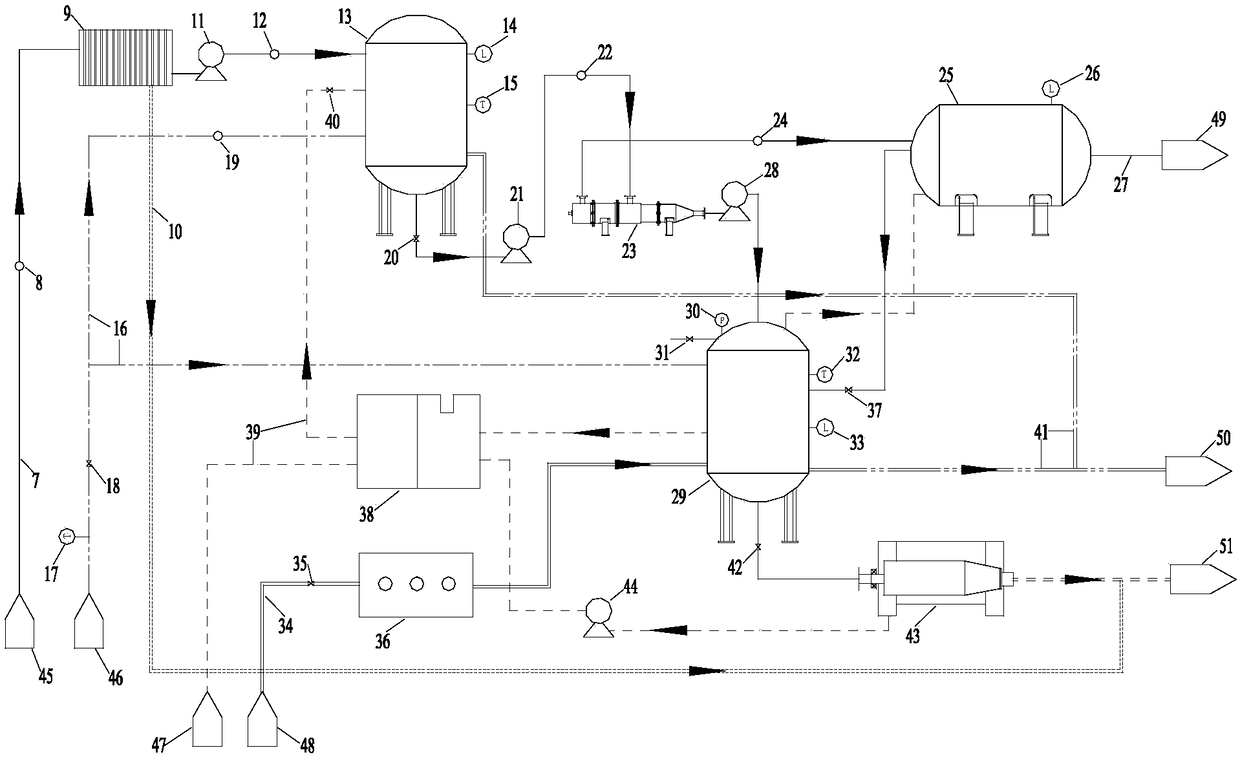
[0055] Such as figure 1As shown, the high-efficiency combined oily sludge cleaning system of this embodiment includes: conditioning device 1, mechanical separation device 2, ozone auxiliary cleaning device 3, oil-water separation device 4, mud-water separation device 5 and cleaning water reuse device 6 The oily sludge 41 is connected to the grid 9 through the oily sludge input pipeline 7, the single screw pump 11 is connected to the heating and stirring tank 13, and the steam 42 is connected to the heating and stirring tank 13 through the steam input pipeline 16, and the heating and mixing tank 13 is output through steam The pipeline 41 is connected to the steam treatment device 50, and the oily sludge is tempered through the grid 9 and the heating and stirring tank 13; Mechanically separate the oily sludge, the mechanical separation device 2 is connected to the ozone auxiliary cleaning device 3 and the oil-water separation device 4 respectively; the oil-water separation devic...


PUM


Abstract

The invention discloses an efficient combined method oil-containing sludge cleaning system, which comprises a tempering device, a mechanical separation device, an ozone auxiliary cleaning device, an oil-water separation device, a mud water separation device and a cleaning water reuse device, wherein the tempering device is connected with the mechanical separation device; the mechanical separationdevice is respectively connected with the ozone auxiliary cleaning device and the oil-water separation device; the ozone auxiliary cleaning device is connected with the mud water separation device; the cleaning water reuse device is respectively connected with the ozone auxiliary cleaning device, the mud water separation device and the tempering device, so that the combined method oil-containing sludge cleaning process is completed. The oil-mud-water three-phase separation can be realized; the separation dwell time is reduced; water after the separation is pumped into the cleaning water reusedevice for systematically and cyclically used; the mud is recovered and piled; the oil is recovered and treated; the cost is low; the picking packaging is realized; the treatment efficiency is high; the treatment period is short; the economic resource configuration is reasonable; the sustainable development requirements can be met.

Description

technical field [0001] The invention relates to a treatment technology for oily sludge, in particular to a high-efficiency combined oily sludge cleaning system for oily sludge cleaning. Background technique [0002] The effective disposal of oil sludge generated in the petroleum industry has received more and more attention, and oilfield oil sludge has been listed as hazardous solid waste (HW08) by the state. Current research shows that a large amount of oil sludge will be produced in the process of oil extraction, gathering and refining. Oily sludge usually has the characteristics of high oil content, high viscosity, fine particles, and difficult dehydration, and there are a certain amount of pathogens, heavy metals, and radionuclides in it that are difficult to degrade toxic and harmful substances, which have carcinogenic, teratogenic, and mutagenic effects. If it is not dealt with in time, it will not only cause great harm to the ecological environment, cause resource co...

Claims


Application Information

Patent Timeline
Patent Type & Authority Applications(China)
IPC IPC(8): C02F11/12C02F1/40C02F11/06
CPCC02F1/40C02F11/06C02F11/127
Inventor 朱玲肖楠雷伟香桑义敏孔佳雯王侯兵
Owner BEIJING INSTITUTE OF PETROCHEMICAL TECHNOLOGY
Why Eureka
Try Eureka