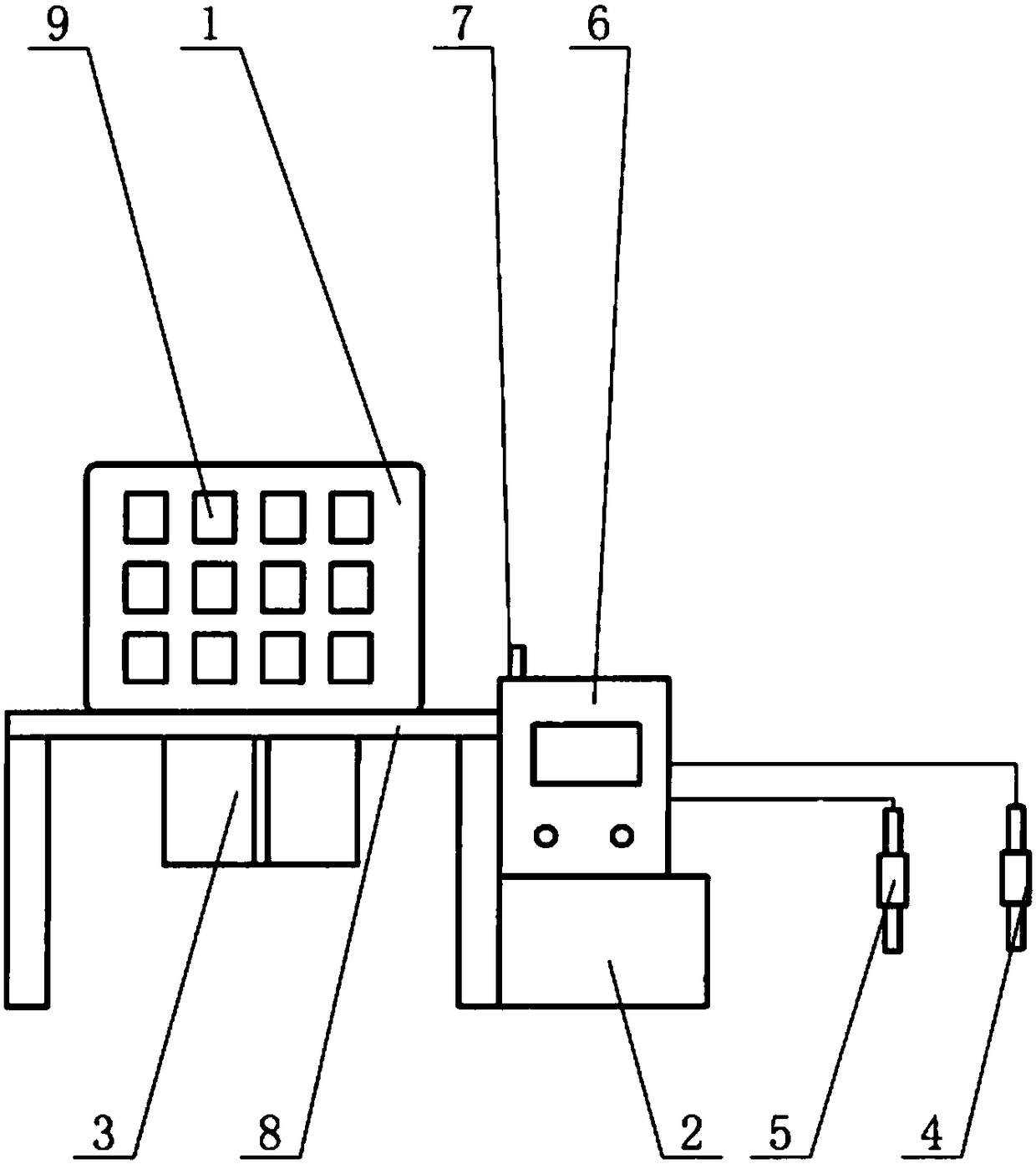
Oil field steam channeling detection device
A detection device, steam channeling technology, applied in circuit devices, battery circuit devices, measurement and other directions to achieve the effects of reducing costs, improving safety, and improving alarm accuracy
- Summary
- Abstract
- Description
- Claims
- Application Information
AI Technical Summary
Problems solved by technology
Method used
Image
Examples
Embodiment 1
[0037] In this embodiment, the preparation steps of the dye-sensitized solar cell are:
[0038] Step 1, Cleaning
[0039] Cut the Ti metal sheet of the counter electrode substrate and the FTO substrate of the photoanode substrate to the same size, and then ultrasonically clean them with acetone, ethanol, and deionized water in sequence;
[0040] Step 2, prepare the photoanode
[0041] a) Preparation of Fe 2 o 3 / CuO / TiO 2 composite nanofiber
[0042] Place 0.5g glacial acetic acid in methanol to form a 4ml solution, then put iron acetate, copper carbonate and tetrabutyl titanate into it to obtain solution A, wherein tetrabutyl titanate is 0.667g, iron acetate, Copper carbonate is determined according to the ratio; 0.375g of polyvinylpyrrolidone is dissolved in 4ml of anhydrous methanol to obtain solution B;
[0043] Add solution A to solution B dropwise at a constant speed. After the dropwise addition, stir vigorously for 10 hours to obtain the spinning precursor; absorb...
Embodiment 2
[0056] In this embodiment, the preparation steps of the dye-sensitized solar cell are:
[0057] Step 1, Cleaning
[0058] Cut the Ti metal sheet of the counter electrode substrate and the FTO substrate of the photoanode substrate to the same size, and then ultrasonically clean them with acetone, ethanol, and deionized water in sequence;
[0059] Step 2, prepare the photoanode
[0060] a) Preparation of Fe 2 o 3 / CuO / TiO 2 composite nanofiber
[0061] Place 0.5g glacial acetic acid in methanol to form a 4ml solution, then put iron acetate, copper carbonate and tetrabutyl titanate into it to obtain solution A, wherein tetrabutyl titanate is 0.667g, iron acetate, Copper carbonate is determined according to the ratio; 0.375g of polyvinylpyrrolidone is dissolved in 4ml of anhydrous methanol to obtain solution B;
[0062] Add solution A to solution B dropwise at a constant speed. After the dropwise addition, stir vigorously for 10 hours to obtain the spinning precursor; absorb...
Embodiment 3
[0075] In this embodiment, the preparation steps of the dye-sensitized solar cell are:
[0076] Step 1, Cleaning
[0077] Cut the Ti metal sheet of the counter electrode substrate and the FTO substrate of the photoanode substrate to the same size, and then ultrasonically clean them with acetone, ethanol, and deionized water in sequence;
[0078] Step 2, prepare the photoanode
[0079] a) Preparation of Fe 2 o 3 / TiO 2 composite nanofiber
[0080] Place 0.5g of glacial acetic acid in methanol to form a 4ml solution, then put iron acetate and tetrabutyl titanate into it to obtain solution A, wherein the tetrabutyl titanate is 0.667g, and the iron acetate is determined in proportion; 0.375g of polyvinylpyrrolidone was dissolved in 4ml of anhydrous methanol to obtain solution B;
[0081] Add solution A to solution B dropwise at a constant speed. After the dropwise addition, stir vigorously for 10 hours to obtain the spinning precursor; absorb an appropriate amount of spinnin...
PUM
| Property | Measurement | Unit |
|---|---|---|
| Particle size | aaaaa | aaaaa |
| Thickness | aaaaa | aaaaa |
| Diameter | aaaaa | aaaaa |
Abstract
Description
Claims
Application Information
 - R&D
- Intellectual Property
- Life Sciences
- Materials
- Tech Scout
- Unparalleled Data Quality
- Higher Quality Content
- 60% Fewer Hallucinations
Browse by: Latest US Patents, China's latest patents, Technical Efficacy Thesaurus, Application Domain, Technology Topic, Popular Technical Reports.
© 2025 PatSnap. All rights reserved.Legal|Privacy policy|Modern Slavery Act Transparency Statement|Sitemap|About US| Contact US: help@patsnap.com

