Valve-controlled hydraulic transmission system applied to exoskeleton robot

An exoskeleton robot, hydraulic transmission technology, applied in the direction of fluid pressure actuation device, manipulator, mechanical equipment, etc., can solve the problems of large ineffective energy consumption, increase energy consumption, increase manufacturing cost, etc., achieve less potential failure points, work Fast, easy-to-control effects

Active Publication Date: 2018-09-11
GUIYANG HAIZHILI HYDRAULIC CO LTD
View PDF13 Cites 4 Cited by
  • Summary
  • Abstract
  • Description
  • Claims
  • Application Information

AI Technical Summary

Problems solved by technology

[0010] 1. Low transmission efficiency
The electro-hydraulic servo valve is a control element that sacrifices energy consumption in exchange for high response speed. When the flow rate needs to be precisely controlled (corresponding to the speed control of the oil cylinder), it must maintain a certain pressure loss at the valve port, and there is pilot oil consumption (for micro For hydraulic transmission, the pilot fuel consumption accounts for a large proportion), and the hydraulic system controlled by electro-hydraulic servo valve generally has the problems of low transmission efficiency and large ineffective energy consumption
The large ineffective energy consumption will cause the system to heat up, and additional heat dissipation measures are required, which further increases energy consumption and causes the overall shape and weight of the exoskeleton robot to increase, and the battery life is shortened.
[0011] 2. The control is complicated, and there are too many factors restricting its function realization, which reduces the adaptability to working conditions and working reliability
Moreover, due to the variety of human motion postures, the control based on preset algorithms is difficult to fully cover all possible motion postures of the wearer, which affects its adaptability to working conditions
[0012] 3. The manufacturing cost is too high, restricting its marketing
Due to the need to configure multiple servo valves, multiple sensors, and a powerful processor (or microcomputer), on the one hand, to reserve installation space for these components, it will lead to an increase in overall shape and weight; on the other hand, These components themselves are of high value, further increasing the manufacturing cost
Although in the research and development stage, we can focus on performance and put cost control in the second place, but in order to form a product, controlling the manufacturing cost is a problem that needs to be faced sooner or later

Method used


Image

  • Valve-controlled hydraulic transmission system applied to exoskeleton robot
  • Valve-controlled hydraulic transmission system applied to exoskeleton robot
  • Valve-controlled hydraulic transmission system applied to exoskeleton robot

Examples


Embodiment 1

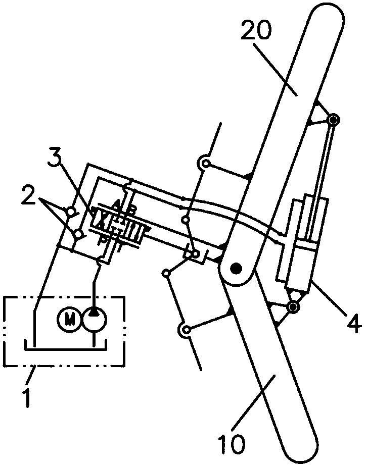
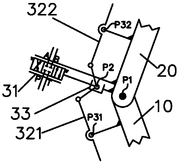
[0086] see figure 1, is a schematic diagram of an embodiment in which the present invention is applied to an exoskeleton robot to assist the knee joint. The first mechanical arm (mechanical lower leg A-1) and the second mechanical arm (mechanical thigh A-2) of the exoskeleton robot are hinged together through the P1 point (note: the first mechanical arm and the second mechanical arm are collectively referred to as mechanical arm; the actual design of the mechanical arm may adopt a more complex articulation method, but the present invention focuses on the hydraulic transmission and its control scheme, and the mechanical structure is only used to express the design intent). When the exoskeleton robot is worn on the human body, the human calf and human thigh are respectively close to the first mechanical arm (mechanical calf A-1) and the second mechanical arm (mechanical thigh A-2).

[0087] The present invention includes a hydraulic oil source 1, an oil replenishment check valv...

Embodiment 2

[0110] See attached Figure 4 It is a schematic diagram of an embodiment of the present invention that adopts a single-acting oil cylinder to assist the knee joint, and it is combined with the attached figure 1The only difference is that the single-acting oil cylinder 41 is used to assist, and the manual servo valve 3 can use a three-position three-way manual servo valve 31, which has at least one oil inlet, one oil return port, and one oil outlet. It acts on the oil inlet chamber of the oil cylinder 41 , and the oil outlet has a fuel supply check valve 2 connected to the oil tank 110 . Of course, the manual servo valve 3 can also be used as figure 1 The three-position four-way servo valve 32 is shown, with one outlet plugged and unused, making it equivalent to a three-position three-way manual servo valve, although this is not preferred.

[0111] A single-acting oil cylinder is used to assist, and its basic working principle is the same as that of a double-acting oil cylind...

Embodiment 3

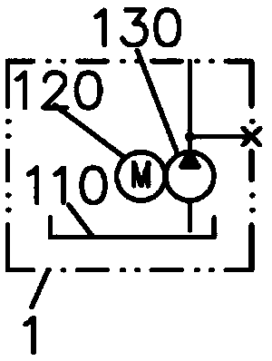
[0115] See attached Figure 5 It is a schematic diagram of the second embodiment of the hydraulic oil source of the present invention, which is attached to image 3 The only difference is that the outlet of the hydraulic pump 130 is connected to the high-pressure accumulator 140 through a check valve for maintaining pressure. For hydraulically driven exoskeleton robots that require high response speed, the hydraulic oil source used should be a constant pressure oil source, and a high-pressure accumulator is installed to help increase the instantaneous maximum oil supply flow. The high-pressure accumulator can also act as a buffer effect.


PUM


Abstract

The invention discloses a valve-controlled hydraulic transmission system applied to an exoskeleton robot. The valve-controlled hydraulic transmission system comprises a hydraulic oil source, a manualservo valve, an oil-filling one-way valve, an oil cylinder, a first mechanical arm and a second mechanical arm which is hinged to the first mechanical arm. The hydraulic oil source comprises a servo motor, a hydraulic pump and an oil tank; the servo motor drives the hydraulic pump; the hydraulic pump sucks oil from the oil tank to be supplied to the manual servo valve; the manual servo valve has mechanical position feedback to form closed-loop control; an oil outlet of the manual servo valve communicates with an oil inlet cavity of the oil cylinder and further communicates with the oil tank through the oil-filling one-way valve; and the manual servo valve comprises a reversing valve, a reversing control mechanism connected with the reversing valve, and a control mechanism travel limiting device. Under the joint cooperation effect of the manual servo valve, the oil-filling one-way valve and the oil cylinder, the control mode of the exoskeleton robot is simplified, the working reliability and safety are effectively improved, the working speed is increased while energy consumption is reduced, and the production and using cost is reduced.

Description

technical field [0001] The invention relates to the technical field of mechanical engineering, and more specifically relates to a valve-controlled hydraulic transmission system applied to an exoskeleton robot. Background technique [0002] Exoskeleton robot is a human-machine collaboration device worn on the human body, which has broad application prospects in military, logistics, emergency rescue, and assisting the disabled. Many institutions at home and abroad have carried out research and development of exoskeleton robots and obtained phased research results. [0003] According to the transmission form, there are three types of exoskeleton robots: electric transmission (motor-driven reducer or screw), hydraulic transmission (hydraulic oil-driven cylinder), and pneumatic transmission (compressed air-driven cylinder). Among them, hydraulic transmission has become the mainstream transmission scheme for heavy-duty (load-bearing) exoskeleton robots due to its high power densi...

Claims


Application Information

Patent Timeline
Patent Type & Authority Applications(China)
IPC IPC(8): F15B11/08F15B13/04F15B1/02B25J9/00
CPCF15B1/02F15B11/08F15B13/0401B25J9/0006
Inventor 侯刚王海波曹雄曹明远杨毛王佩瑾
Owner GUIYANG HAIZHILI HYDRAULIC CO LTD
Why Eureka
Try Eureka