air energy water heater

A technology of air energy water heaters and heat exchange tanks, applied in fluid heaters, heat exchange equipment, machines/engines, etc., can solve the problems of limited contact area, slow temperature rise, unstable heating effect of air water heaters, etc., to achieve The air flow is fast, the temperature is concentrated, and the effect of avoiding external water seepage

Active Publication Date: 2020-06-12
日照新睿招商发展有限公司
View PDF7 Cites 0 Cited by
  • Summary
  • Abstract
  • Description
  • Claims
  • Application Information

AI Technical Summary

Problems solved by technology

[0004] The object of the present invention is to provide an air energy water heater to solve the problem that the heating effect of the air water heater proposed in the above background technology is very unstable in the severe cold environment in the north, and even the internal components of the equipment stop working due to the temperature being too low After entering the water heater, the contact area with water is limited, and the temperature rise rate is relatively slow.

Method used


Image

  • air energy water heater
  • air energy water heater
  • air energy water heater

Examples


Embodiment 1

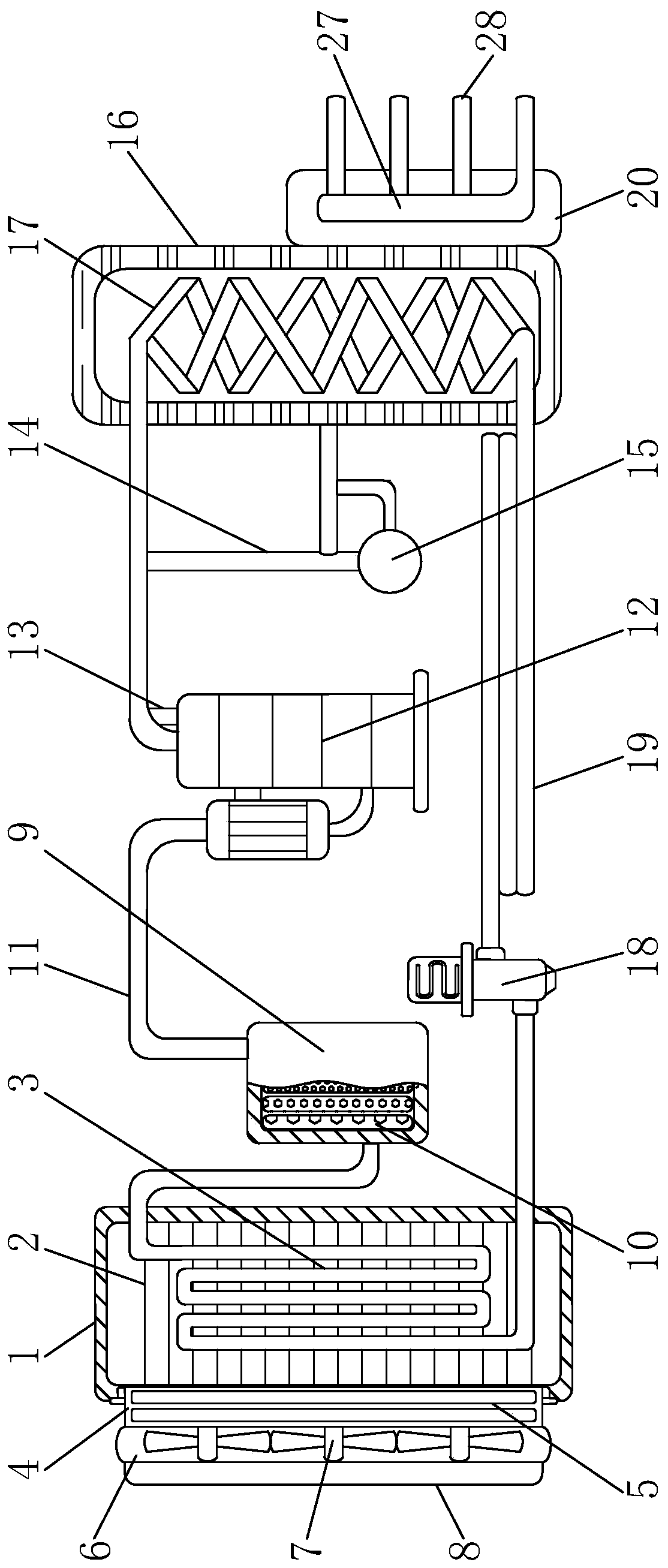
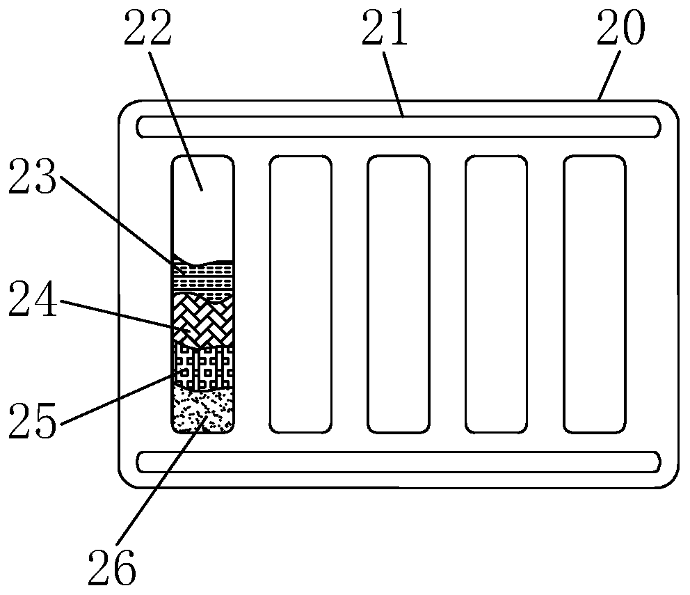
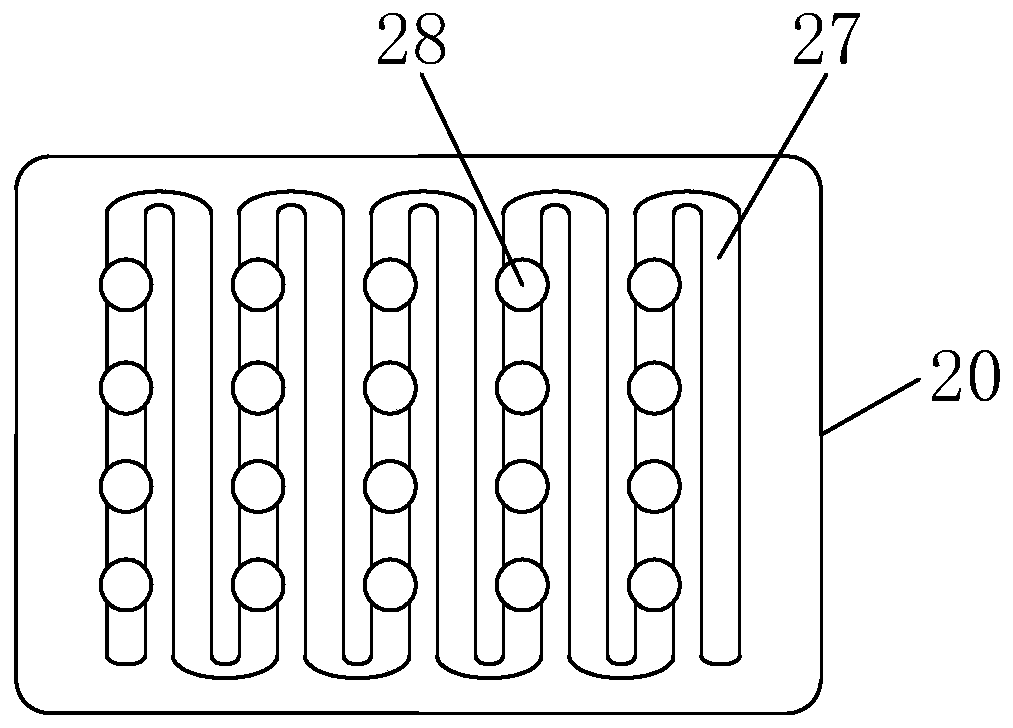
[0043] see Figure 1-3 , the present invention provides a technical solution: an air energy water heater, including an evaporator 1, a drying tank 9, a heat exchange tank 16 and a transition water tank 20, the inner wall of the evaporator 1 is installed with an isolation sealing plate 2, and the evaporator 1 is connected to the The isolation and sealing plates 2 are welded and connected, and the isolation and sealing plates 2 are evenly distributed along the vertical direction of the evaporator 1, and the thickness of the isolation and sealing plates 2 is equal, and the isolation and sealing plates 2 are closely fitted, and the isolation and sealing plates 2 The interior of the evaporator 1 is isolated into a closed space to ensure that the evaporation work of the external airflow in the evaporator 1 is not affected by the external environment, and to ensure the overall sealing effect of the evaporator 1. An evaporation contact tube 3 is arranged in the middle of the evaporator...

Embodiment 2

[0046] see Figure 4-9 , this embodiment further includes the following features on the basis of embodiment 1: the water inlet pipe is connected with a filter pump. The filter pump is used to take water from wells, rivers or lakes. The water outlet of the filter pump can be connected to the water pipe through a three-way joint, and the connection between the water pipe and the three-way joint is connected in series. valve.

[0047] The filter pump includes a motor 91 , a pump casing 92 and a water wheel 96 rotatably installed in the pump casing and driven by the motor.

[0048] A pump cover 911 is connected to the lower end of the motor, and the pump cover is sealingly connected to the upper end of the pump casing with an open upper end, and a pump chamber is formed between the pump casing and the pump cover.

[0049] The middle of the lower end of the pump housing is integrally connected with a circular pipe-shaped water inlet pipe portion 921 , and the side wall of the pum...


PUM


Abstract

The invention discloses an air-energy water heater. The air-energy water heater comprises an evaporator, a drying tank, a heat exchange water tank and a transition water tank, wherein an isolation sealing plate is installed on the inner wall of the evaporator, and the evaporator is connected with the isolation sealing plate in a welding manner; an evaporation contact pipe is arranged at the middleof the evaporator, and a first filter plate is installed at the left side of the evaporator; the first filter plate is installed at the left side of the evaporator in an embedding manner; a filter screen is arranged in the first filter plate, and the first filter plate is fixedly connected with the filter screen; water absorption sponge is arranged in the drying tank, and the drying tank is located at the right side of the evaporator; a heat exchange pipe is installed in the heat exchange water tank, and the heat exchange water tank is located at the right side of a condensation water collection ball; and cutting plates are fixed to the upper side and the lower side of the back surface of the transition water tank, and the transition water tank is located below the right side of the heatexchange water tank. The air-energy water heater can be used in a cold environment, and is rapid in heating and stable in running.

Description

technical field [0001] The invention relates to the technical field of water heater equipment, in particular to an air energy water heater. Background technique [0002] Air energy water heater, also known as air source heat pump water heater, air energy water heater absorbs the low-temperature heat in the air, gasifies it through fluorine medium, then compresses it through a compressor, pressurizes it and heats it up, and then converts it through a heat exchanger to heat water, using compression The final high-temperature heat energy is used to heat the water temperature, and the air-energy water heater has the characteristics of high efficiency and energy saving. [0003] However, the modern air water heater is very stable in the warm south, but in the cold environment of the north, the heating effect of the air water heater will be very unstable, and even due to the low temperature, the internal components of the equipment will stop working and the air will enter The wat...

Claims


Application Information

Patent Timeline
Patent Type & Authority Patents(China)
IPC IPC(8): F24H4/04F24H9/00F24H9/18F25B39/02F25B43/00F28F19/01F04D13/06F04D15/00F04D29/22F04D29/70
CPCF04D13/06F04D15/0005F04D15/0088F04D29/2222F04D29/708F24H4/04F24H9/0005F24H9/1809F25B39/02F25B43/00F28F19/01
Inventor 李为松
Owner 日照新睿招商发展有限公司
Why Eureka
Try Eureka