
Time domain measuring method of linear frequency modulation signal frequency characteristic parameters

A technology of linear frequency modulation signal and frequency characteristics, which is applied in the direction of frequency measurement device, frequency to pulse sequence conversion, etc., which can solve the problems of low efficiency, large amount of data, slow calculation speed, etc.

Active Publication Date: 2018-09-11
UNIV OF ELECTRONICS SCI & TECH OF CHINA
View PDF10 Cites 6 Cited by
  • Summary
  • Abstract
  • Description
  • Claims
  • Application Information

AI Technical Summary

Problems solved by technology

This type of processing method has high precision, but has a large amount of data, slow calculation speed, and low efficiency, and cannot meet the requirements of short processing time such as instantaneous test stimulus generation and real-time dynamic response.

Method used

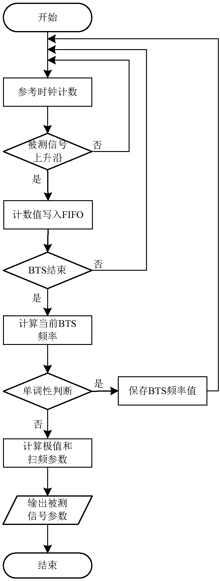
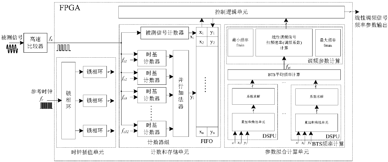

Image

  • Time domain measuring method of linear frequency modulation signal frequency characteristic parameters
  • Time domain measuring method of linear frequency modulation signal frequency characteristic parameters
  • Time domain measuring method of linear frequency modulation signal frequency characteristic parameters

Examples


Embodiment

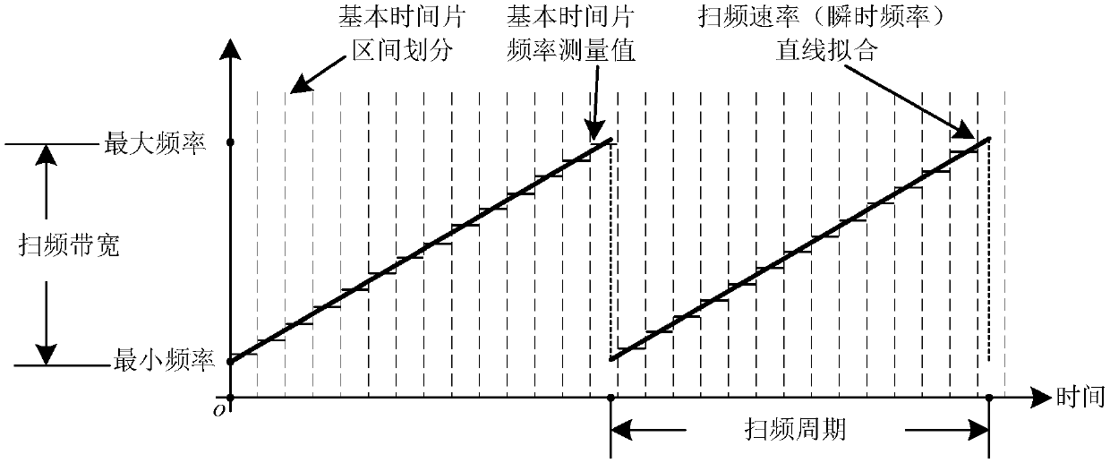
[0029] figure 1 It is a principle schematic diagram of a time-domain measurement method for frequency characteristic parameters of a chirp signal according to the present invention.

[0030] In this example, if figure 1 As shown, the vertical dotted line divides the measured chirp signal into several basic time slices of fixed width, and uses the time domain counting method to count the measured chirp signal and the reference clock signal in each basic time slice interval. According to the change law presented by the measured linear frequency modulation signal and the reference clock, the least square method is used for fitting, and the following is obtained: figure 1 As shown by the short horizontal line in the middle, it represents the average value of the carrier frequency of the basic time slice. By repeating this step, the average frequency value of multiple basic time slices can be obtained. Although the measured frequency value is the average frequency of each basic ...

example

[0054] Taking a chirp signal with a starting frequency of 60MHz, a bandwidth of 80MHz, and a frequency sweep period of 50kHz as an example, divide each BTS into 200ns, measure the frequencies of 100 BTSs continuously, and then perform minimum By square fitting, the instantaneous frequency expression is f=799846T+59991827, and the goodness of fit is 0.9998. According to the instantaneous frequency expression, the frequency sweep rate is 3.9993×10 12 Hz / s, minimum frequency 59.992MHz, maximum frequency 139.993MHz, sweep bandwidth 80.001MHz, sweep cycle 49.99kHz, measurement error ≤ 0.02%, which can meet the needs of fast and accurate measurement of frequency characteristic parameters.


PUM


Abstract

The invention discloses a time domain measuring method of linear modulation frequency signal frequency characteristic parameters. The method includes; performing waveform shaping and level conversionon a measured linear frequency modulation signal by employing a high-speed comparator, and then inputting the shaped and converted digital square wave signal to a field programmable gate array (FPGA)for calculation and measurement; in the FPGA, performing time interpolation on a clock signal by employing an on-chip phase-locked loop of the FPGA, counting the digital square wave signal and a reference clock signal through a counter, performing parameter fitting by employing the least squares method, and obtaining an average frequency value of the measured linear frequency modulation signal ina basic time slice interval; and then obtaining an instantaneous frequency expression of the measured linear frequency modulation signal through a least-squares fitting mode according to the average frequency value obtained by a series of measurements so that parameters including the sweeping frequency rate, the maximum frequency and the minimum frequency are calculated.

Description

technical field [0001] The invention belongs to the technical field of signal processing and signal measurement, and more specifically relates to a time-domain measurement method for frequency characteristic parameters of linear frequency modulation signals. Background technique [0002] Linear frequency modulation (LFM) signals, also known as chirp signals, are a signal regime widely used in various types of contemporary radars. The linear frequency modulation signal is to use a triangle wave or a sawtooth wave to modulate the carrier, so that a modulated signal in which the signal frequency changes linearly periodically with time is generated. Chirp signal is a kind of spread spectrum modulation signal with large bandwidth and time width. The radar using the linear frequency modulation signal can also be called pulse compression radar, which has a large effective detection range while ensuring high resolution, so it has been widely used in various occasions such as height...

Claims


Application Information

Patent Timeline
Patent Type & Authority Applications(China)
IPC IPC(8): G01R23/10
CPCG01R23/10
Inventor 张朋李力黄建国
Owner UNIV OF ELECTRONICS SCI & TECH OF CHINA
Learn More