Methane chloride recycling and feeding process and device

A methane chloride and feeding technology, which is applied in chemical instruments and methods, organic chemistry, disproportionation separation/purification of halogenated hydrocarbons, etc., can solve the problems of high equipment investment and complicated process, so as to save operating costs and reduce operating temperature , the effect of reducing energy consumption

Active Publication Date: 2018-09-14
HUBEI XINGRUI SILICON MATERIAL CO LTD
View PDF4 Cites 5 Cited by
  • Summary
  • Abstract
  • Description
  • Claims
  • Application Information

AI Technical Summary

Problems solved by technology

However, the recovery of methane chloride still needs to be condensed and then vaporized, and the process is complicated and the equipment investment is high.

Method used


Image

  • Methane chloride recycling and feeding process and device

Examples


Embodiment 1

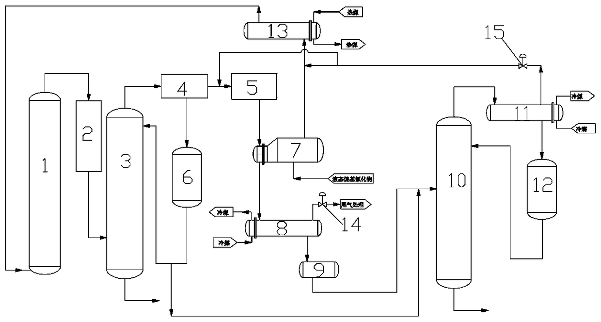
[0023] A device for recovering and feeding methane chloride. Reactor 1 is connected to dust removal system 2, dust removal system 2 is connected to dust removal tower 3, dust removal tower 3 is connected to cooling system 4, and cooling system 4 is connected to vaporizer 7 via compression system 5 , The vaporizer 7 is connected to the condenser 8, the condenser 8 is connected to the refining tower 10 via the buffer tank 9, the refining tower 10 and the top are connected to the reflux tank 12 via the partial condenser 11, and the reflux tank 12 is connected to the refining tower 10 via a pipeline.

[0024] The condenser 11 is connected to the heater 13 through a pipeline one way, and the heater 13 is connected to the reactor 1; one way is merged with the cooling system 4 and then connected to the compression system 5.

[0025] The cooling system 4 is connected to a storage tank 6, the storage tank 6 is connected to the dust removal tower 3 all the way, and the other way is connected ...

Embodiment 2

[0028] The gas mixture containing methane chloride from the top of the reactor 1 is removed by the dust removal system 2 to remove most of the dust, and then washed by the dust removal tower 3 to remove high boiling point substances and fine powder. The material at the top of the dust removal tower 3 is condensed to 5°C by the cooling system 4, and the condensate enters the storage tank 6, part of the material in the storage tank 6 is used as a washing liquid, and about 24t / h of the material goes to the refining tower 10. The non-condensable gas in the cooling system 4 is about 17t / h, and the pressure is 0.25MPa (G). The decompression system 5 compresses to 1.0MPa (G) and 100°C. Liquid methane chloride of 11t / h enters the vaporizer 7 and vaporizes through heat exchange with the methane chloride from the compression system 5, and the temperature is about 30°C. The methane chloride from the compression system 5 then enters the condenser 8 to be further condensed to -10°C, the non...

Embodiment 3

[0030] The gas mixture containing methane chloride from the top of the reactor 1 is removed by the dust removal system 2 to remove most of the dust, and then washed by the dust removal tower 3 to remove high boiling point substances and fine powder. The material at the top of the dust removal tower 3 is condensed to 4° C. through the cooling system 4, and the condensate enters the storage tank 6, part of the material in the storage tank 6 is used as a washing liquid, and about 25.6t / h of material goes to the refining tower 10. The non-condensable gas in the cooling system 4 is about 11.2t / h and the pressure is 0.2MPaG. The compression system 5 compresses to 1.1MPa(G) and 130°C. Liquid methane chloride 11.3t / h enters the vaporizer 7 and vaporizes through heat exchange with the methane chloride from the compression system 5 at a temperature of about 30°C. The methane chloride from the compression system 5 then enters the condenser 8 to be further condensed to -10°C, the non-conde...


PUM


Abstract

The invention provides a methane chloride recycling and feeding process and device. The process comprises the following specific steps: removing the vast majority of dust from a methane-chloride-containing gas mixture from the top of a reactor via a dust removal system, and then washing the gas mixture via a dust removal tower to remove high-boiling-point substances and fine powder; after condensing a material on the top of the dust removal tower via a cooling system, taking part of the material as a cleaning solution, and feeding the other part of the material to a refining tower; feeding noncondensable gas in the cooling system to a compressing system; carrying out heat exchange on compressed gas and liquid methane chloride via a vaporizer, vaporizing the liquid methane chloride, coolingand condensing the compressed gas, and then feeding the compressed gas into a condenser for further condensing, carrying out tail gas removal treatment on noncondensable gas in the condenser, and feeding condensate to a buffering tank; enabling the methane chloride of the buffering tank and the methane chloride of a storage tank to enter the refining tower together; and enabling a gas phase on the top of the refining tower to enter a partial condenser for partial condensing, and feeding the condensate into a refluxing tank and totally refluxing the condensate into the refining tower. The methane chloride can be recycled effectively, the main content is higher than 99.5%, moreover, the process is simple, the investment of equipment is low, and energy conservation and consumption reductionare implemented.

Description

Technical field [0001] The invention belongs to the technical field of methylchlorosilane production, and specifically relates to a process and device for the recovery and feeding of raw materials for methylchlorosilane production. Background technique [0002] In industrial production, methylchlorosilane is mainly synthesized by direct method, and the main raw materials used are silicon powder and methane chloride. The current domestic synthesis level of methylchlorosilane is low, and the conversion rate of methane chloride in a single pass is only 30-50%, which is not converted. The methane chloride needs to be recycled. The traditional methane chloride recycling process is to condense the synthesized product in the reactor after dust removal, the condensate is removed to the crude monomer tower, the non-condensable gas is compressed to a certain pressure, and the methane chloride extracted from the crude monomer tower After being condensed, the material also goes to the methy...

Claims


Application Information

Patent Timeline
Patent Type & Authority Applications(China)
IPC IPC(8): C07C19/03C07C17/38C07C17/383
CPCC07C17/38C07C17/383C07C19/03
Inventor 高英王文金沈维云刘英波尚剑
Owner HUBEI XINGRUI SILICON MATERIAL CO LTD
Why Eureka
Try Eureka