Bottom blowing reduction device and reduction method using device

A horizontal direction, furnace body technology, applied in the field of bottom blowing reduction device, can solve the problems of inability to improve reduction efficiency, oxygen content powder particle size control and energy consumption, push rod power and boat stress enhancement, low production efficiency, etc. problems, to avoid scale increase and agglomeration effect, shorten the temperature zone and furnace body length, and solve the effect of low production efficiency

Pending Publication Date: 2018-09-14
孙院军 +2
View PDF10 Cites 4 Cited by
  • Summary
  • Abstract
  • Description
  • Claims
  • Application Information

AI Technical Summary

Problems solved by technology

From the overall process, there are four problems; the first is that the yield loss is relatively large due to the existence of two-stage reduction and two screenings, and the total yield does not exceed 98%; The secondary temperature rises and falls, which consumes a lot of energy; the third is that the two-stage reduction requires hydrogen to enter and exit twice, and most of the reduction equipment is not equipped with a hydrogen recovery system, resulting in a large loss of hydrogen
Fourth, the production efficiency is low, and a complete molybdenum powder reduction process takes more than 20 hours
If the production efficiency is only improved under the existing technology and equipment conditions, lengthening the reduction zone is a better choice, but it will lead to an increase in the number of pushing boats, increased resistance, and a significant increase in the power of the push rod and the stress on the boats.
For the rotary or mesh-belt reduction, although the influence of the boat structure on the reduction atmosphere of the powder micro-region is weakened compared with the boat reduction, it does not solve the problem of the coexistence of the reducing gas and the water vapor generated by the reaction. Therefore, Cannot improve reduction efficiency, oxygen content, powder particle size control and energy consumption

Method used


Image

  • Bottom blowing reduction device and reduction method using device
  • Bottom blowing reduction device and reduction method using device

Examples


Embodiment 1

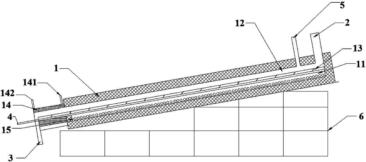
[0055] The furnace body 1 of the device is arranged laterally, and the included angle with the horizontal direction is 15°. The length of the heating zone is 6 meters, divided into 5 temperature zones, the length of each temperature zone is 1.2 meters, and the temperature is set at 480-510-540-550-530°C. The furnace chamber width is 220 mm, and the gas chamber 11 has a height of 20 mm. The porous plate 13 is made of molybdenum metal, and the diameter of the through holes is about 20 microns.

[0056] Molybdenum trioxide is added from the silo of the feed port 2, and enters the material chamber 12 through the flow controller and the material leveler. The feeding speed is 150g / min, the material thickness in the material chamber 12 is 2.5mm, and the reduction time is 6.5 hours. During the reduction process, hydrogen gas is introduced to keep the positive pressure in the gas chamber 11 at 0.05 MPa. After the reduction is complete, the product enters the cooling section and is c...


PUM

PropertyMeasurementUnit
angleaaaaaaaaaa
pore sizeaaaaaaaaaa

Abstract

The invention provides a bottom blowing reduction device. The bottom blowing reduction device comprises a furnace body, a feed port, a discharge port, a reduction gas inlet and a reduction gas outlet;the furnace body is transversely arranged, and forms a certain included angle with the horizontal direction; in the length direction of the furnace body, a gas cavity and a material cavity are formedin the furnace body; the gas cavity and the material cavity are separated by a porous plate; the feed port is formed in one higher end of the furnace body; and the reduction gas inlet and the reduction gas outlet both communicate with the gas cavity. The invention further provides a method for bottom blowing reduction by using the device; and materials to be reduced are fed in the material cavityfrom the feed port, slowly move downwards along the inclined furnace body under coaction of the gravity and the reduction gas, and are finally reduced and output from the discharge port. The method has no need to use a push rod or a conveying belt for driving a boat container to move, so that the boat container and a conveying device are omitted.

Description

technical field [0001] The invention relates to the technical field of metallurgical equipment, in particular to a bottom blowing reduction device and a reduction method using the device. Background technique [0002] Metals in nature are mainly oxides and sulfides. The extraction of these metals generally goes through a process of enrichment, transformation and separation, such as ore dressing, pyrometallurgy, and hydrometallurgy. Metals that exist in the form of sulfides generally need to be calcined to form oxides. Whether it is a natural oxide or an oxide obtained by roasting, after purification, a reduction process is basically required to obtain pure metal powder, which becomes the raw material for the preparation of metal products. There are two main methods of reduction: one is solid-solid reduction, such as reducing iron powder with carbon powder; the other is gas-solid reduction, such as reducing molybdenum oxide and tungsten oxide with hydrogen, and reducing cop...

Claims


Application Information

Patent Timeline
Patent Type & Authority Applications(China)
IPC IPC(8): C22B5/12C22B34/34C22B34/36
CPCC22B5/12C22B34/34C22B34/36
Inventor 孙院军史慧群孙紫昂
Owner 孙院军
Why Eureka
Try Eureka