
pt modified fe2o3 wrapped cufeo2 photocathode and its preparation method

A photocathode, fe2o3 technology, applied in the field of photoelectrochemistry, can solve the problems of electrical conductivity and light transmittance damage, unfavorable photogenerated carrier transport, large difference in work function, etc., to achieve high photocurrent density and improve photolysis. Hydrogen production efficiency from water and the effect of low production temperature

Inactive Publication Date: 2019-11-08
SUZHOU INST OF INDAL TECH
View PDF7 Cites 0 Cited by
  • Summary
  • Abstract
  • Description
  • Claims
  • Application Information

AI Technical Summary

Problems solved by technology

But the current common CuFeO 2 The preparation methods of thin-film photoelectrodes, such as sol-gel method, electrochemical deposition method, solid-state reaction method, etc., have some defects. On the one hand, the preparation temperature is relatively high, generally above 700°C or even 1000°C, and continuous annealing treatment is required for several times. Ten hours, while the conductivity and light transmittance of commonly used transparent conductive substrates, such as ITO glass, are easily damaged under high temperature treatment, and annealing at 700 ° C may even completely destroy ITO glass; on the other hand, Although CuFeO 2 The energy band structure is very suitable as a photocathode, but its work function is quite different from that of the currently recognized most efficient noble metal hydrogen production catalysts such as Pt, and it is easy to form an upturn at the interface that is not conducive to the transport of photogenerated carriers. Barrier

Method used


Image

  • pt modified fe2o3 wrapped cufeo2 photocathode and its preparation method
  • pt modified fe2o3 wrapped cufeo2 photocathode and its preparation method
  • pt modified fe2o3 wrapped cufeo2 photocathode and its preparation method

Examples


preparation example Construction

[0047] Pt-modified Fe 2 o 3 Coated CuFeO 2 The preparation method of photocathode comprises the following steps:

[0048] Step 1. Weigh the prepared CuFeO by weight ratio 4:1-5:1 2 After the powder and iodine powder are mixed, they are put into the acetone solution to prepare an electrophoretic deposition suspension with a weight ratio of 1:1-1:1.5, and the mixed suspension is ultrasonically oscillated in an ultrasonic cleaner for 15-20 minutes to obtain a mixed homogeneous suspension;

[0049] Step 2. Make a piece with an area of ​​2-4cm 2 , surface cleaned ITO conductive glass substrate 1 and an area of ​​8-10cm 2 Put the graphite electrode sheet in parallel into the suspension prepared in step 1. The distance between the ITO conductive glass substrate 1 and the graphite electrode sheet is 1-1.5cm. The ITO conductive glass substrate 1 is connected to the positive electrode, and the graphite electrode sheet is connected to the negative electrode. The stabilized power su...

Embodiment 1

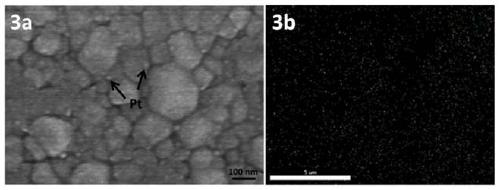
[0056] Such as Figure 1-9 As shown, Pt modified Fe 2 o 3 Coated CuFeO 2 Photocathode, layer by layer from the surface down to Pt catalyst particle layer 3, Fe 2 o 3 Coated CuFeO 2 Particle film layer 2, ITO conductive glass substrate 1, Pt particles in Pt catalyst particle layer 3 are deposited on Fe 2 o 3 Coated CuFeO 2 Particle film layer 2 surface, Fe 2 o3 Coated CuFeO 2 Fe in particle film layer 2 2 o 3 with CuFeO 2 form a wrapping structure between them, and the Fe on the surface 2 o 3 in CuFeO 2 A transition layer is formed between the Pt catalyst particle layer 3 .

[0057] Deposit a layer of CuFeO on the ITO conductive glass substrate 1 by electrophoretic deposition 2 granular layer, followed by a sol-gel method on CuFeO 2 The surface of the granular layer was treated with plastic rejection for 5 times, and Fe was obtained after annealing. 2 o 3 Coated CuFeO 2 Particle film layer 2, and finally, using the photoreduction method on the Fe 2 o 3 Coa...


PUM

PropertyMeasurementUnit
thicknessaaaaaaaaaa
diameteraaaaaaaaaa

Abstract

The invention relates to a Pt modified Fe2O3 coated CuFeO2 photocathode which comprises a Pt catalyst particle layer, a Fe2O3 coated CuFeO2 particle film layer and an ITO conducting glass substrate layer by layer downward from the surface, wherein Fe2O3 and CuFeO2 in the Fe2O3 coated CuFeO2 particle film layer form a coating structure; Fe2O3 on the surface forms a transitional layer between FeO2 and the Pt catalyst particle layer, an upwarp barrier at the interface is eliminated, and the photo current density and the hydrogen production efficiency of the photocathode are improved. The Pt modified Fe2O3 coated CuFeO2 photocathode and a preparation method overcome the defects that the preparation temperature of an existing CuFeO2 film photoelectrode is high, the conductivity and transparencyof the ITO conducting glass substrate layer are easily damaged and the upwarp barrier is easily formed between CuFeO2 and the Pt catalyst particle layer, and has the characteristics of being good instability, visible-light responsive, large in photo current density, high in turn-on voltage and the like.

Description

technical field [0001] The invention relates to the field of photoelectrochemical technology, in particular to Pt modified Fe 2 o 3 Coated CuFeO 2 Photocathode and preparation method, CuFeO can be prepared at low temperature on ITO conductive glass substrate 2 Thin film photocathode. Background technique [0002] Hydrogen energy has the advantages of high efficiency, cleanliness, and renewability, and is one of the widely researched alternative technologies for fossil energy. Since Fujishima et al pioneered the use of titanium dioxide (TiO 2 ) electrodes are used in photolysis of water to produce hydrogen, and finding semiconductor photoelectrodes with high stability and high hydrogen production efficiency has become a hot research topic. Compared with the photoanode that generates oxygen in the photo-water splitting reaction, the photocathode that directly evolves hydrogen on the surface has less research results, mainly because the number of p-type semiconductor speci...

Claims


Application Information

Patent Timeline
Patent Type & Authority Patents(China)
IPC IPC(8): C25B11/08C25B1/04
CPCC25B1/04C25B1/55C25B11/051C25B11/093Y02E60/36
Inventor 程小荣吴阳江刘昊从金亮张明玉包晨阳
Owner SUZHOU INST OF INDAL TECH
Learn More