
Chip resistor and manufacturing method thereof

A manufacturing method and technology of resistors, applied in the direction of resistors, resistor parts, non-adjustable metal resistors, etc., can solve the problem of reducing the service life of resistors and safety and reliability, and the large size of metal plate resistors affects the service life of products And other problems, to achieve the effect of excellent heat dissipation, excellent mechanical properties, and improve production efficiency

Pending Publication Date: 2018-09-14
常德思高技术有限公司
View PDF1 Cites 8 Cited by
  • Summary
  • Abstract
  • Description
  • Claims
  • Application Information

AI Technical Summary

Problems solved by technology

The metal plate resistance obtained in this invention has the disadvantages of large volume, high inductance, and difficulty in automatic production, and the heat dissipation of the obtained resistor is slow, which greatly reduces the service life and safety reliability of the resistor, and the obtained resistor is easy to cause The difference in resistance usually requires multiple mechanical or laser methods to adjust the resistance value of the resistor sheet, so mechanical or laser marks are brought, which is a big defect for the impact of current. When the current strikes, it will affect the service life of the product, it is not easy to realize automatic production, and the production efficiency is reduced

Method used


Image

  • Chip resistor and manufacturing method thereof
  • Chip resistor and manufacturing method thereof
  • Chip resistor and manufacturing method thereof

Examples


Embodiment Construction

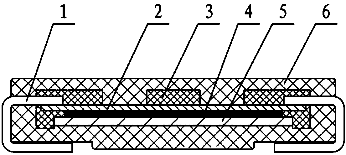
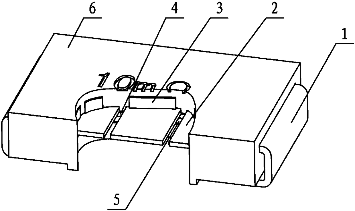
[0054] Such as Figure 1-2 As shown, the present invention provides a chip resistor, including a resistor chip 2, an inner shell 3 wrapped on the surface of the resistor chip 2, a heat sink 5 bonded to the surface of the resistor chip 2 through an insulating heat-conducting glue 4, and an outermost layer The shell 6 is connected to the two ends of the resistance sheet 2 and the electrode pin 1 is outside the shell 6. The inner shell 3 has a hollow part for coating the insulating heat-conducting glue 4.

[0055] According to the present invention, the hollow part of the inner shell 3 is smaller than the size of the heat sink 5, and the two ends of the inner shell 3 are also provided with steps to support the heat sink 5, so as to ensure that the heat sink 5 does not contact the resistor plate 2, and ensure the high precision of the equipment and instruments. Data Accuracy.

[0056] The resistance sheet 2 of the present invention is an alloy material, and the alloy material is ...


PUM


Abstract

The invention provides a chip resistor. The chip resistor comprises a resistor sheet, an inner shell which wraps the surface of the resistor sheet, a heat sink bonded to the surface of the resistor sheet through an insulating thermal conductive adhesive, an outer shell at the outermost layer and electrode pins connected with the two ends of the resistor sheet and located outside the outer shell, and the inner shell is provided with a hollowed-out part for coating the insulating thermal conductive adhesive. A manufacturing method of the chip resistor includes the steps of blanking the resistorsheet and the electrode pins, then processing and connecting the resistor sheet and the electrode pins to form a resistor body, conducting rough adjustment and fine adjustment on a resistance value ofthe resistor body, packaging for the first time to form the inner shell, blanking the heat sink, bonding the heat sink to the resistor sheet through the insulating thermal conductive adhesive, packaging for the second time, cutting and bending the electrode pins to form a side U shape, and finally conducting post-processing to obtain the chip resistor. According to the chip resistor, after roughadjustment and fine adjustment are conducted on the resistance value of the resistor body, packaging is conducted for the first time, a layer of inner shell wraps the resistor body to ensure that theheat sink is not contact with the resistor sheet, and the obtained chip resistor has high precision, fast heat dissipation, long service life, safety and reliability, and high product yield.

Description

technical field [0001] The invention belongs to the technical field of electronic devices, in particular to a chip resistor and a manufacturing method thereof. Background technique [0002] In the fields of inverter air conditioners, new energy electric vehicles, aerospace, power adapters, etc., they are all applied to current detection resistors for real-time detection of current. The following functions are realized by applying the current detection resistor: (1) Overcurrent protection, monitor the current flowing through the output terminal of the motor or power supply, and adjust the output current if the load changes; (2) Multi-phase load balance, monitor each current-carrying The amperage value on the line and affects the real-time response, so as to ensure the reliable operation of the circuit over a wide temperature range. This type of current detection resistor has the characteristics of small resistance and high precision. Its resistance is generally at the millio...

Claims


Application Information

Patent Timeline
Patent Type & Authority Applications(China)
IPC IPC(8): H01C1/032H01C1/08H01C1/084H01C1/144H01C1/148H01C3/00H01C17/02H01C17/28
CPCH01C1/032H01C1/08H01C1/084H01C1/144H01C1/148H01C3/00H01C17/02H01C17/28
Inventor 刘显生
Owner 常德思高技术有限公司
Learn More