Wireless power transmission device with constant current output feature

A technology of wireless power transmission and constant current output, which is applied in circuit devices, transmission systems, near-field transmission systems, etc., can solve problems such as increased complexity and cost, reduced efficiency, and large loss, and achieves reduced complexity and simple structure , the effect of small loss

Pending Publication Date: 2018-09-21
NORTHWESTERN POLYTECHNICAL UNIV
View PDF0 Cites 2 Cited by
  • Summary
  • Abstract
  • Description
  • Claims
  • Application Information

AI Technical Summary

Problems solved by technology

At present, the commonly used high-frequency power supply is mainly designed based on the bridge inverter power supply. The traditional bridge inverter power supply has a complex structure, and requires an external PWM signal generator to drive the switch tube. Usually, a frequency tracking circuit is also required to realize the wireless power transmission system. Frequency tracking function, the drive of the inverter power supply is complicated, and the loss is relatively large. It is usually used in the high-power field of the kilowatt level, and the application effect is not good in the small and medium power field; for electronic products that use electric energy, some occasions require wireless power. The output current of the transmission device does not change with the change of the load, that is, the wireless power transmission device is required to maintain a constant output current under different output power conditions (the load changes), or only a small change, such as electric There is a constant current charging stage in the car charging process
At present, most wireless power transmission devices cannot automatically realize constant voltage output under different load conditions, but realize constant current output by adding a DC / DC converter in the subsequent stage, which leads to system complexity and cost. increase, the efficiency is reduced, and the wide input voltage range of the DC / DC converter also poses great difficulties to its design

Method used


Image

  • Wireless power transmission device with constant current output feature
  • Wireless power transmission device with constant current output feature
  • Wireless power transmission device with constant current output feature

Examples


specific Embodiment approach

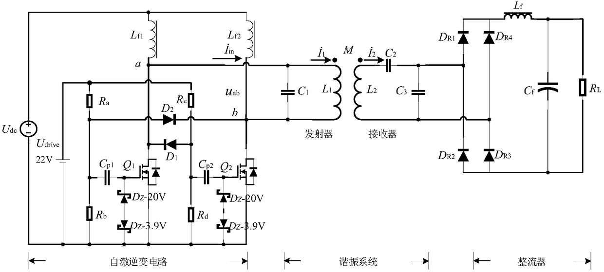
[0059] The present invention has two input power interfaces, one of which is the drive power U drive =22V, the other is the power supply U dc = 36V;

[0060] A self-excited inverter circuit, including 2 identical MOS transistors Q 1 and Q 2 , the model is C2M0040120D; 2 identical inductive choke coils L f1 and L f2 , L f1 =L f2 =220uH; 4 resistors R a ~R d , between resistance values ​​satisfying R a = R c = 300Ω, R b = Rd =10kΩ; 2 identical diodes D 1 and D 2 , the model is FR607; two identical zener diodes Dz-20V with a withstand voltage of 20V, the model is 1n5357B; two identical zener diodes with a withstand voltage of 3.9V Dz-3.9V, the model is 1n5335A; two identical capacitors C p1 and C p2 , C p1 =C p2 = 100nF.

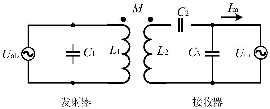
[0061] An electromagnetic resonant system consists of a transmitter and a receiver, the transmitter has a capacitance C 1 and transmitting coil L 1 Composition, C 1 =300nF,L 1 =9uH; the receiver consists of receiving coil L 2 and capacitan...


PUM


Abstract

The invention relates to a wireless power transmission device with a constant current output feature. A self-excitation inverter circuit is adopted for designing an inverter power supply. According tothe design scheme of the self-excitation inverter circuit, self-driving of a switching tube can be achieved, and extra PWM generators and driving circuits are omitted. The wireless power transmissiondevice is simple in structure, and can also automatically achieve the resonant frequency trace function; moreover, the switching tube works in the zero-voltage switching-on and switching-off state, the loss is small, and the complexity of the inverter circuit is lowered greatly. An electromagnetic resonance system with the constant current output feature is adopted; single-capacitance parallel compensation topology is adopted for the transmitting end of the electromagnetic resonance system, dual-capacitance serial and parallel compensation topology is adopted for the receiving end of the electromagnetic resonance system, constant current output of the wireless power transmission device can be basically achieved under different load conditions simply through three compensation capacitanceelements, and the addition of a rear-level DC / DC converter is omitted.

Description

technical field [0001] The invention belongs to the technical field of wireless power transmission, and relates to a wireless power transmission device with a constant current output characteristic, in particular to a magnetic coupling resonant wireless power transmission device with a constant current output characteristic. Background technique [0002] Since the second industrial revolution, human society has entered the era of electrification, ranging from power grids and high-voltage lines all over the world to various household electrical equipment. The transmission of electric energy is mainly through point-to-point direct contact transmission of metal wires. This "wired" transmission method has brought many problems. Due to problems such as friction and aging, sparks are easily generated during power transmission, which in turn affects the life of electrical equipment and the safety of electricity [1] . In addition, the traditional wired power transmission method ca...

Claims


Application Information

Patent Timeline
IPC IPC(8): H02J50/12H04B5/00
CPCH02J50/12H04B5/79Y02B70/10
Inventor 王尧刘卫国刘云天蒋峻峰魏晨露
Owner NORTHWESTERN POLYTECHNICAL UNIV
Why Eureka
Try Eureka