
Method for controlling elevator tractor

A technology of elevator traction machine and control method, which is applied in the direction of speed/torque control of a single motor, estimation/correction of motor parameters, elevators, etc. performance issues

Active Publication Date: 2018-09-25
SHANGHAI MITSUBISHI ELEVATOR CO LTD
View PDF5 Cites 7 Cited by
  • Summary
  • Abstract
  • Description
  • Claims
  • Application Information

AI Technical Summary

Problems solved by technology

However, regardless of the voltage injection method or the current injection method, the prerequisite for tracking the salient pole characteristics of the surface-mounted motor is that the applied pulse voltage and pulse current can excite the salient pole effect of the motor, that is, the direct axis inductance and the quadrature axis The inductance shows a large difference
For some surface-mounted motors, the applied voltage and current must be large enough to cause the saliency effect of the motor, and the large pulse vibration voltage and pulse current will cause serious fluctuations in the output torque of the motor, which will seriously affect the performance of the motor. work performance, destroying the comfort of elevator operation
[0009] Therefore, the existing control methods of these permanent magnet synchronous motors cannot be well applied to the control of surface-mounted permanent magnet synchronous motors with relatively low salient pole ratios in elevator systems.
In view of the deficiencies of the existing technology, the field of elevator control urgently needs to propose a position sensorless control method that can realize a permanent magnet synchronous traction machine with a low saliency ratio.

Method used


Image

  • Method for controlling elevator tractor
  • Method for controlling elevator tractor
  • Method for controlling elevator tractor

Examples


Embodiment 1

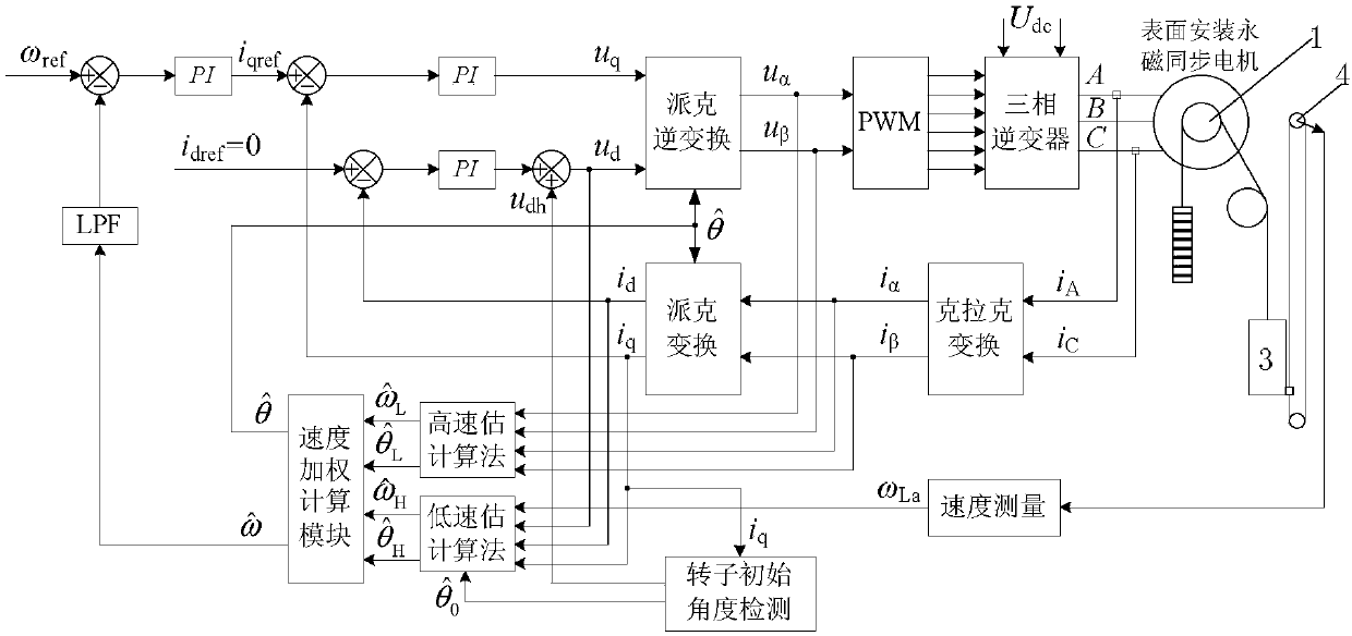
[0094] Such as figure 2 As shown, the traction machine drives the car 3 to move up and down through the main rope;

[0095] The speed limiter encoder 4 is installed on the flywheel shaft of the speed limiter, and the car 3 drives the flywheel of the speed limiter to rotate through the speed limiter rope, so that the speed limiter encoder 4 rotates to generate a coded signal output, and the car 3 moves The faster, the higher the frequency of the encoded signal output by the speed limiter encoder 4;

[0096] A control method for an elevator traction machine, comprising the following steps:

[0097] Step A. Obtain the initial rotor angle of the elevator traction machine

[0098] Step B. Obtain the low-speed rotor speed when the traction machine runs below the set speed and low speed rotor angle And the middle and high speed rotor speed when the traction machine is running higher than the set speed and medium and high speed rotor angle

[0099] Step C. According to t...

Embodiment 2

[0106] Based on Embodiment 1, the initial rotor angle of the traction machine is obtained in step A The method is:

[0107] A1. Apply the set amplitude higher than the set frequency ω on the direct axis of the stator of the traction machine r The high-frequency sinusoidal signal of the traction machine is used to perform Clarke transformation and Parker transformation on the output current of the traction machine stator to obtain the quadrature axis component of the traction machine stator current;

[0108] A2. Pass the quadrature-axis component of the stator current of the traction machine through a second-order band-pass filter to select one of which is higher than the set frequency ω r The AC component of the AC component is multiplied by the unit sine signal to obtain the modulation signal;

[0109] A3. Use a band-stop filter to filter out the AC component in the modulation signal to obtain an error signal containing the rotor angle error;

[0110] A4. Use the PI contr...

Embodiment 3

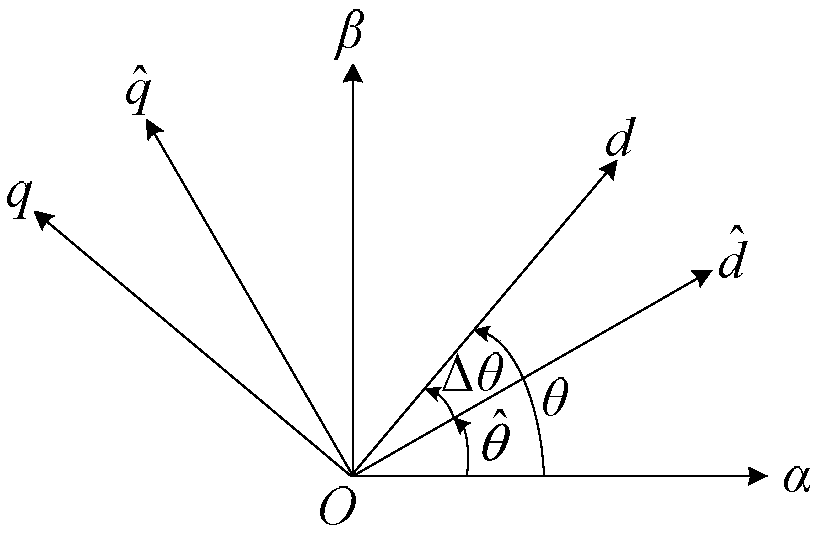
[0114] Based on the elevator traction machine control method in Embodiment 1, establish a coordinate system relationship diagram, such as image 3 As shown, d-q is the actual synchronous rotating coordinate system, In order to estimate the rotor synchronous rotating coordinate system, α-β is the actual two-phase stationary coordinate system, and the estimated position error is defined θ is the actual rotor angle, is the estimated value of the rotor angle in the full speed range;

[0115] Such as Figure 4 As shown, the initial rotor angle of the traction machine is obtained in step A The method is:

[0116] Step A10. Under the condition that the traction machine is stationary and the brake device is activated, estimate the rotor synchronous rotation coordinate system Inject the signal:

[0117] Among them, u qh is the signal applied on the quadrature axis of the stator, u dh is the sinusoidal signal applied on the direct axis of the stator, U h for u dh Amplit...


PUM


Abstract

The invention discloses a method for controlling an elevator tractor, which comprises the steps of obtaining an initial rotor angle of the elevator tractor; obtaining the rotor speed and rotor angle of the tractor at low speed running and the rotor speed and rotor angle of the tractor at medium and high speed running; obtaining a full speed range rotor speed estimated value and a full speed rangerotor angle estimated value of the tractor by adopting a smooth weighting factor method according to the rotor speed and the rotor angle of the tractor at low speed running and the rotor speed and rotor angle of the tractor at medium and high speed running, and performing closed-loop control on the speed of the tractor. The method for controlling the elevator tractor can realize motor encoder freecontrol for the tractor in an elevator system within the full speed range and reduce the cost of the system.

Description

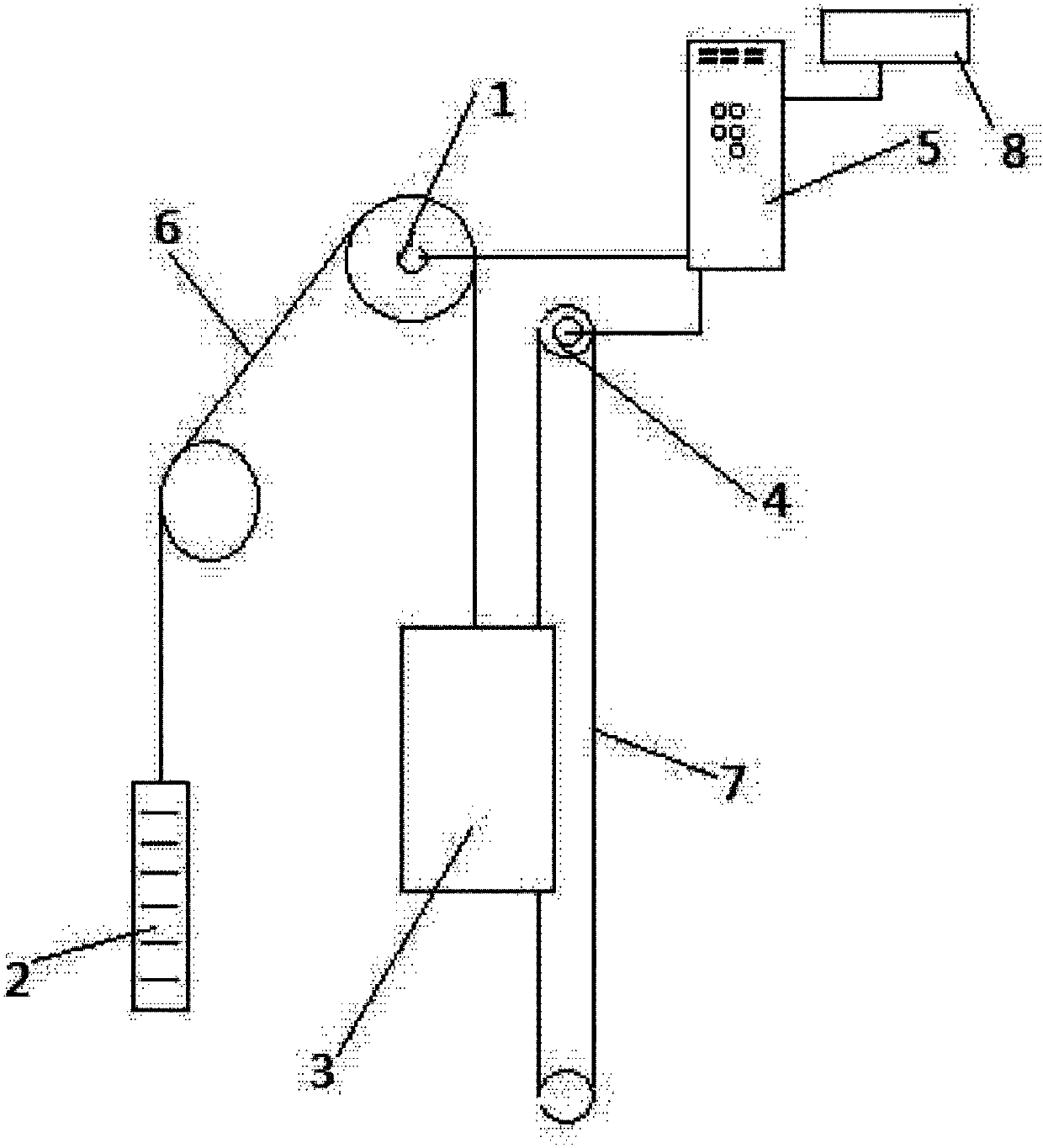
technical field [0001] The invention relates to an elevator permanent magnet synchronous motor control technology, in particular to an elevator traction machine control method. Background technique [0002] There is an existing elevator safety control system, such as figure 1 As shown, it includes motor encoder 1, counterweight 2, car 3, speed governor encoder 4, safety controller 5, main wire rope 6, speed governor wire rope 7 and GSM module 8. It adopts double encoders of motor encoder 1 and speed limiter encoder 4, and the double encoders are connected to safety controller 5 through a shielded cable, and safety controller 5 encodes the encoded signals generated by motor encoder 1 and speed limiter encoder 4 Take measurements. The motor encoder 1 detects the running state of the traction machine in real time, and the speed limiter encoder 4 detects the running state of the car in real time. The safety controller 5 detects the running status of the traction machine 3 and...

Claims


Application Information

Patent Timeline
IPC IPC(8): H02P6/08H02P23/14B66B1/30
CPCB66B1/308H02P6/08H02P23/14
Inventor 王晗朱武标刘玉兵奚良徐亚军钱敏陈玉东何晓光
Owner SHANGHAI MITSUBISHI ELEVATOR CO LTD
Learn More