Cold accumulation water tank of refrigeration house refrigerating system

A refrigeration system and cold storage technology, which is applied to household refrigeration devices, applications, coolers, etc., can solve the problems of low refrigeration efficiency, difficulty in oil return, and difficulty in automation, etc., and achieve the effect of strong cold storage capacity and simple structure

Pending Publication Date: 2018-09-28
北京中冷高科制冷设备有限公司
View PDF6 Cites 0 Cited by
  • Summary
  • Abstract
  • Description
  • Claims
  • Application Information

AI Technical Summary

Problems solved by technology

[0003] A liquid ammonia refrigeration system is generally composed of a refrigeration unit, an ammonia oil separator, a high-pressure liquid receiver, a condenser, a low-pressure circulating liquid storage tank, an oil collector, an ammonia pump, and a cooling fan. The cost is low, but this kind of system has complex pipelines, difficult operation and management, and requires high professional level of operators. At the same time, because it is difficult to realize automation, the system requires operators to be on duty 24 hours a day for operation and management
In addition, there are problems such as difficult oil return and easy leakage of liquid ammonia in the direct evaporation system. Once ammonia gas leaks, it is very easy to cause an explosion accident
The investment cost of the fluorine refrigeration system is high at the initial stage of construction, and it is also a direct evaporation system. The freon needs to be mixed with lubricating oil. When the vertical height or the total length of the copper pipe connected to the outdoor unit of the refrigeration system increases, it will cause serious oil return in the refrigeration system. smooth, resulting in a significant reduction in cooling efficiency and a substantial increase in power consumption
Moreover, Freon refrigerants have no obvious characteristics when they leak, so the operating costs will be greatly increased in leak repair and refrigerant filling

Method used


Image

  • Cold accumulation water tank of refrigeration house refrigerating system
  • Cold accumulation water tank of refrigeration house refrigerating system
  • Cold accumulation water tank of refrigeration house refrigerating system

Examples


Embodiment Construction

[0065] In order to make the object, technical solution and advantages of the present invention clearer, the present invention will be further described in detail below in conjunction with the accompanying drawings.

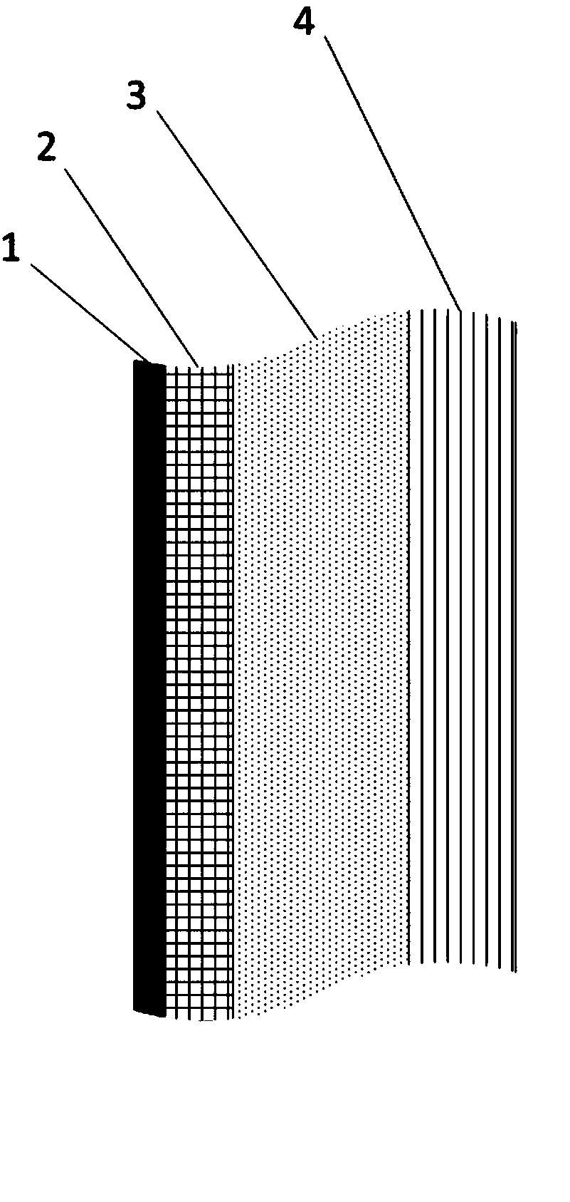
[0066] figure 1 It is a schematic diagram of the multilayer structure of the wall of the cold storage pool according to an embodiment of the present invention. Combine below figure 1 This embodiment will be described.

[0067] In this embodiment, the cold storage pool has a multi-layer structure, which is a carbon steel plate layer 1, a steel frame layer 2, a polyurethane foam layer 3 and a polyurethane sandwich panel layer 4 in sequence. The thickness of the carbon steel plate layer is 0.5-1mm, the thickness of the steel frame layer is 10-15mm, the thickness of the polyurethane foam layer is 150-250mm, and the thickness of the polyurethane sandwich panel layer is 50-150mm.

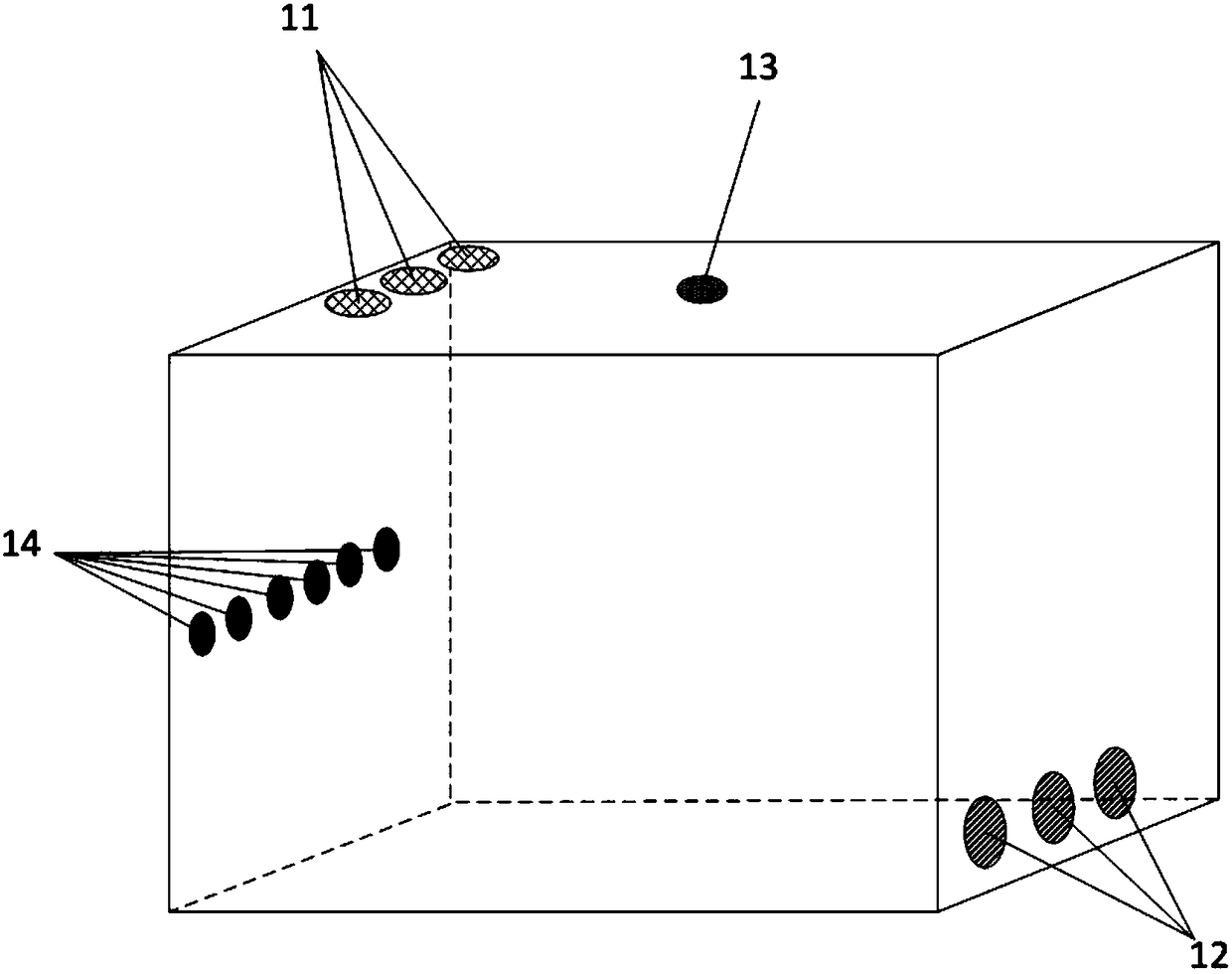
[0068] Such as figure 2 Shown is a schematic diagram of the three-dimensional struct...


PUM


Abstract

The invention discloses a cold accumulation water tank of a refrigeration house refrigerating system. The walls of the cold accumulation water tank are composed of a carbon steel plate layer, a steelframe layer, a polyurethane foaming layer and a polyurethane sandwich panel layer; a secondary refrigerant input port is formed in one side of the upper part of the cold accumulation water tank; a secondary refrigerant output port is formed in the lower part of the side wall of the side opposite to the secondary refrigerant input port; a plurality of partition boards are arranged in the cold accumulation water tank; one side edge of each of the partition boards is connected with the side wall of the cold accumulation water tank; a clearance is reserved between the other side edge of each of the partition boards and the another side wall of the cold accumulation water tank; and the clearances formed between every two adjacent partition boards are not on the same side.

Description

technical field [0001] The invention relates to the technical field of low-temperature refrigeration, in particular to a cold storage pool for a refrigeration system of a cold storage. Background technique [0002] At present, food safety and cold chain construction have entered a period of rapid development. As the central link of low-temperature food circulation, cold storage is crucial to all links of the entire cold chain. For the prior art of large-scale cold storage, liquid ammonia and freon are mainly used as refrigerants for refrigeration. [0003] A liquid ammonia refrigeration system is generally composed of a refrigeration unit, an ammonia oil separator, a high-pressure liquid receiver, a condenser, a low-pressure circulating liquid storage tank, an oil collector, an ammonia pump, and a cooling fan. The cost is low, but this kind of system has complex pipelines, difficult operation and management, and requires high professional level of operators. At the same tim...

Claims


Application Information

Patent Timeline
Patent Type & Authority Applications(China)
IPC IPC(8): F25D13/00F25D23/00
CPCF25D13/00F25D23/00
Inventor 李梅
Owner 北京中冷高科制冷设备有限公司
Why Eureka
Try Eureka