

Hot-melt adhesive
A technology of hot-melt adhesives and symmetry, applied in the direction of adhesives, adhesive types, polyurea/polyurethane adhesives, etc., can solve the problems of low tensile breaking strength and low cohesion of hot-melt adhesives, Achieve the effects of small temperature dependence, stable adhesion, and excellent quality stability
- Summary
- Abstract
- Description
- Claims
- Application Information
AI Technical Summary
Problems solved by technology
Method used
Image

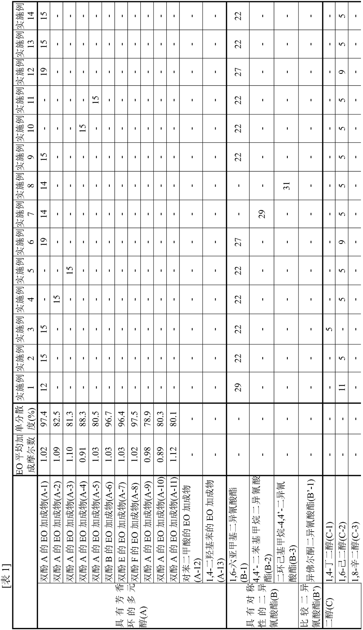
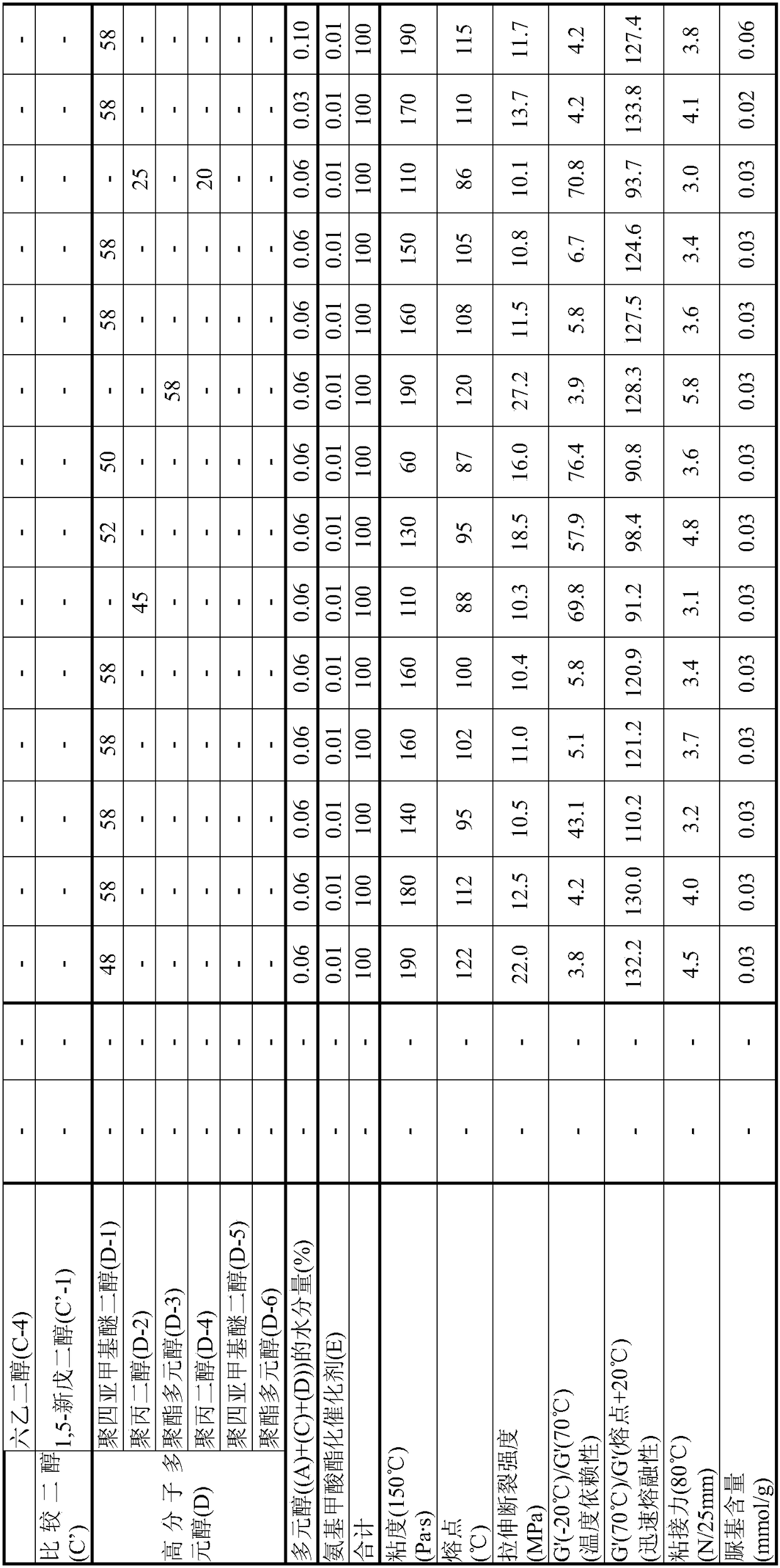
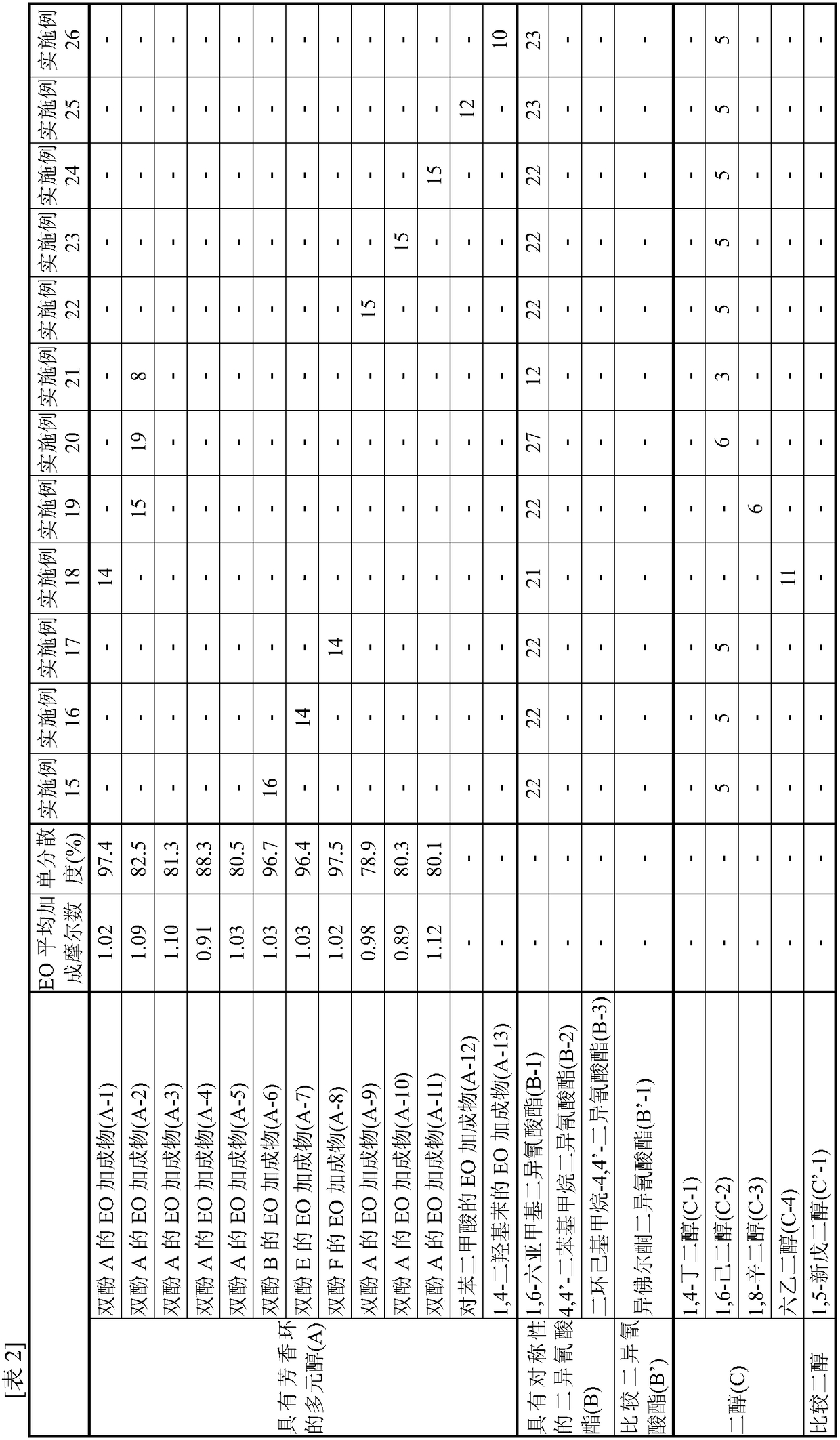
Examples
manufacture example 1
[0100] [Synthesis of EO Adduct of Bisphenol A (A-1)]
[0101] Into a glass autoclave, 137.0 g of toluene (40% relative to bisphenol) and 342.4 g (1.50 mol) of bisphenol A ("bisphenol A" manufactured by Mitsubishi Chemical Corporation) were put into a glass autoclave, and after nitrogen substitution, the temperature was raised to At 75°C, bisphenol A was dispersed in toluene. Thereto was added 2.73 g of a 25% aqueous solution of tetramethylammonium hydroxide.
[0102] Nitrogen replacement was performed again, and EO was added dropwise at 75 to 95° C. and a reaction pressure of 0.2 MPa or less to react. During the reaction, samples were appropriately sampled, the molar distribution of the addition of the reactant to bisphenol was traced by GC, and the reaction was terminated when 1 mole of the addition product reached 0.1% or less. The required EO was 139.9 g (3.18 mol) and the reaction time was 7 hours.
[0103] After the reaction, unreacted EO, a catalyst, a solvent, and th...
manufacture example 2
[0106] [Synthesis of EO adduct of Bisphenol A (A-2)]
[0107] In a glass autoclave, 85.6 g of (A-1) obtained in Example 1 (25 wt % with respect to bisphenol A added later) was charged and melted as a solvent for the reaction system. After heating to 110 degreeC and melting this, bisphenol A 342.4g (1.50 mol) was injected|thrown-in, and after nitrogen substitution, it cooled to 95 degreeC, and bisphenol A was disperse|distributed. Thereto was added 0.30 g of sodium hydroxide.
[0108] Nitrogen replacement was performed again, and EO was added dropwise at 75 to 95° C. and a reaction pressure of 0.2 MPa or less to react. During the reaction, samples were appropriately sampled and the molar distribution of the addition of reactants on bisphenol was followed by GC. The reaction was terminated when 1 mol of the adduct reached 0.1% or less. The required EO was 150.5 g (3.42 mol) and the reaction time was 7 hours.
[0109] After the reaction, the catalyst was neutralized with phos...
manufacture example 3
[0112] [Synthesis of EO adduct of Bisphenol A (A-3)]
[0113] The reaction was carried out in the same manner as in Production Example 2, except that the amount of EO to be added dropwise in Production Example 2 was 154.0 g (3.50 mol), and the reaction was terminated when 1 mol of the adduct reached 0.1% or less.
[0114] After the reaction, the catalyst was neutralized with phosphoric acid, and unreacted EO was distilled off at 130 to 160° C. under reduced pressure to obtain an EO adduct of bisphenol A (A-3).
[0115] As a result of analyzing this (A-3) by GC, the average number of moles of EO added per hydroxyl group of the obtained (A-3) was 1.10, and the monodispersity was 81.3%.
PUM
| Property | Measurement | Unit |
|---|---|---|
| melting point | aaaaa | aaaaa |
Abstract
Description
Claims
Application Information