Composite nanofiber filter membrane

A nanofiber and composite filtration technology, applied in the field of air purification and filtration, can solve the problems of low filtration efficiency, large air resistance, and short service life of filter membranes, and achieve the effects of long service life, increased air circulation path, and wide application value.

Inactive Publication Date: 2018-10-09
FOSHAN RIRISHENG TECH CO LTD
View PDF5 Cites 4 Cited by
  • Summary
  • Abstract
  • Description
  • Claims
  • Application Information

AI Technical Summary

Problems solved by technology

At present, the nanofibers spun by electrospinning have a solid circular cross-section, bead shape, flat or ribbon shape, etc. Although the existing nanof

Method used


Image

  • Composite nanofiber filter membrane

Examples


Example Embodiment

[0020] Example 1:

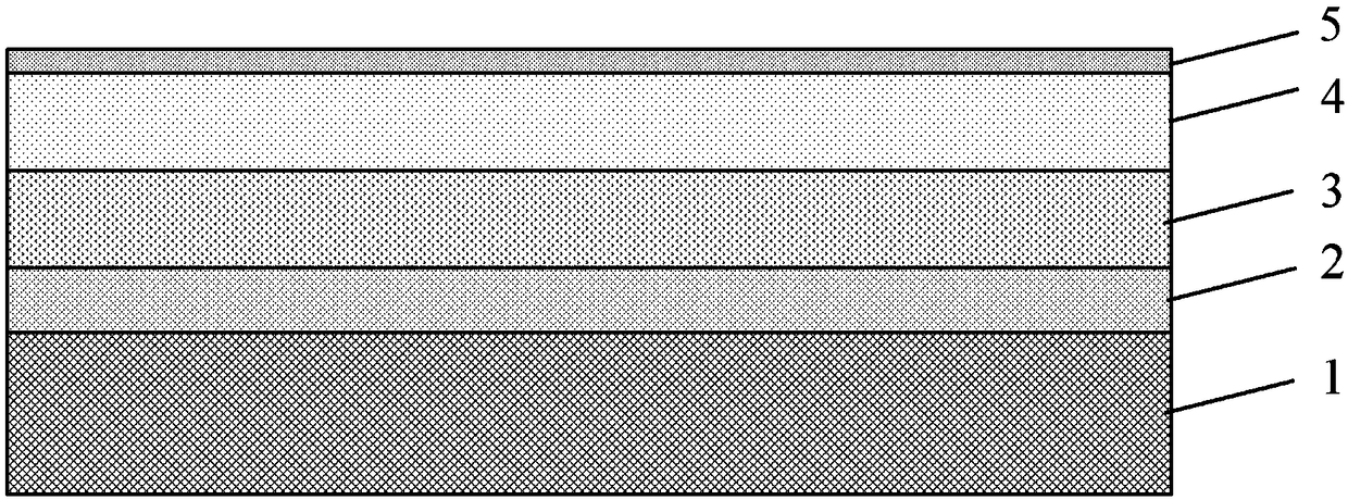
[0021] figure 1 A schematic structural diagram of a nanofiber composite filter membrane according to an embodiment of the present invention is shown. Such as figure 1 As shown, the nanofiber composite filter membrane, the nanofiber composite filter membrane is prepared by electrospinning, and in turn includes: a membrane support layer 1, a non-woven fabric layer 2, a coarse filter layer 3, a nanofiber layer 4, The polyvinylidene fluoride coating 5 is connected to each other; wherein the diameter of the filter holes of the coarse filter layer 3 is 0.1 mm; the nanofiber layer 4 includes a first nanofiber layer 4 and a second nanofiber layer 4 in turn. The fiber layer 4 and the third nanofiber layer 4, the first nanofiber layer 4 is formed on the surface of the coarse filter layer 3; the diameter of the holes between the nanofibers in the first nanofiber layer 4 is 50 μm The diameter of the holes between the nanofibers in the second nanofiber layer 4 is 20 μm,...

Example Embodiment

[0023] Example 2:

[0024] figure 1 A schematic structural diagram of a nanofiber composite filter membrane according to an embodiment of the present invention is shown. Such as figure 1 As shown, the nanofiber composite filter membrane, the nanofiber composite filter membrane is prepared by electrospinning, and in turn includes: a membrane support layer 1, a non-woven fabric layer 2, a coarse filter layer 3, a nanofiber layer 4, The polyvinylidene fluoride coating 5 is connected to each other; wherein the diameter of the filter holes of the coarse filter layer 3 is 1 mm; the nanofiber layer 4 includes a first nanofiber layer 4 and a second nanofiber layer 4 in turn. Layer 4 and a third nanofiber layer 4, the first nanofiber layer 4 is formed on the surface of the coarse filter layer 3; the diameter of the holes between the nanofibers in the first nanofiber layer 4 is 20 μm, The diameter of the holes between the nanofibers in the second nanofiber layer 4 is 1 μm, and the diame...

Example Embodiment

[0026] Example 3:

[0027] figure 1 A schematic structural diagram of a nanofiber composite filter membrane according to an embodiment of the present invention is shown. Such as figure 1 As shown, the nanofiber composite filter membrane, the nanofiber composite filter membrane is prepared by electrospinning, and in turn includes: a membrane support layer 1, a non-woven fabric layer 2, a coarse filter layer 3, a nanofiber layer 4, The polyvinylidene fluoride coating 5 is connected to each other; wherein the diameter of the filter holes of the coarse filter layer 3 is 0.5 mm; the nanofiber layer 4 includes a first nanofiber layer 4 and a second nanofiber layer 4 in turn. The fiber layer 4 and the third nanofiber layer 4, the first nanofiber layer 4 is formed on the surface of the coarse filter layer 3; the diameter of the holes between the nanofibers in the first nanofiber layer 4 is 30 μm The diameter of the holes between the nanofibers in the second nanofiber layer 4 is 10 μm,...


PUM


Abstract

The invention provides a composite nanofiber filter membrane. The composite nanofiber filter membrane is prepared by electrospinning, and sequentially comprises a membrane supporting layer, a nonwovenlayer, a coarse filter layer, a nanofiber layer and a polyvinylidene fluoride coating layer which are mutually connected, wherein the filter hole diameter of the coarse filter layer is 0.1-1mm; the nanofiber layer sequentially comprises a first nanofiber layer, a second nanofiber layer and a third nanofiber layer; the first nanofiber layer is formed on the surface of the coarse filter layer; thediameter of holes between nanofibers in the first nanofiber layer is 20-50 microns, the diameter of holes between nanofibers in the second nanofiber layer is 1-20 microns, and the diameter of holes between nanofibers in the third nanofiber layer is 0.01-1 micron. The nanofiber filter membrane structure is large in specific surface area, an air circulating path is increased, the storage space of particulate matters is increased, and the service life is prolonged while the filtration efficiency of the filter membrane is improved, and the air resistance is lowered.

Description

technical field [0001] The invention relates to the technical field of air purification and filtration, in particular to a nanofiber composite filter membrane. Background technique [0002] Conventional non-woven filter materials have been widely used in various filter products, such as glass fiber, polypropylene fiber, polyester fiber and PTFE fiber, which have been widely used in air purifiers, automotive air conditioning filters and masks. application. However, the fiber diameter of the conventional non-woven filter material is relatively large, and the filter pores formed by the accumulation of fibers are relatively large, and its filtering performance for particles with smaller particle sizes is poor. Therefore, there is a need for more effective air filter materials to filter fine particles. [0003] Nanofibers prepared by electrospinning have the advantages of small fiber diameter, small pore size, high porosity, and large specific surface area. The composite filter...

Claims


Application Information

Patent Timeline
IPC IPC(8): B01D46/54B32B27/02B32B27/32B32B27/12B32B5/02B32B27/36B32B5/26B32B33/00B32B5/06B32B27/30B32B7/12B32B27/28
CPCB01D46/543B32B5/02B32B5/06B32B5/26B32B7/12B32B27/12B32B27/28B32B27/30B32B27/302B32B27/304B32B27/36B32B33/00B32B2262/0238B32B2262/0253B32B2555/00B32B2605/08
Inventor 杨刚坤
Owner FOSHAN RIRISHENG TECH CO LTD
Why Eureka
Try Eureka