Optical-phase conjugation mirror device

An optical phase conjugation and beam technology, applied in optics, optical components, nonlinear optics, etc., can solve problems such as inability to adapt to a wide temperature and wavelength range, achieve compact structure, high extinction ratio, and increase polarization-dependent loss Effect

Pending Publication Date: 2018-10-09
吕婧菲
View PDF5 Cites 2 Cited by
  • Summary
  • Abstract
  • Description
  • Claims
  • Application Information

AI Technical Summary

Problems solved by technology

[0006] The purpose of the present invention is to provide an optical phase conjugate mirror device to solve the technical problem that the polarization rotation optical device in the prior art cannot adapt to a wider temperature and wavelength range

Method used


Image

  • Optical-phase conjugation mirror device
  • Optical-phase conjugation mirror device
  • Optical-phase conjugation mirror device

Examples


Embodiment 1

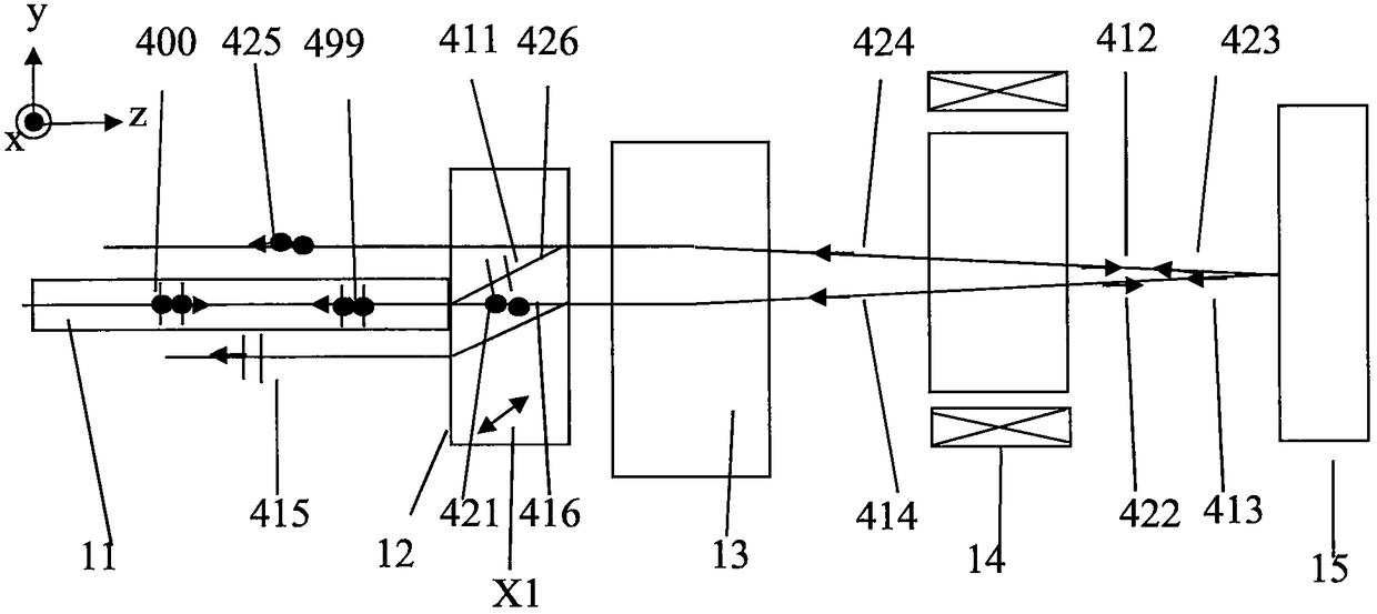
[0059] In Embodiment 1 of the present invention, the optical fiber is a thermally expanded beam optical fiber. The polarized beam splitter includes a polarized beam shifter 12 , the lens is a self-focusing lens 13 ; the reflector is a dielectric optical film plane reflector 15 .

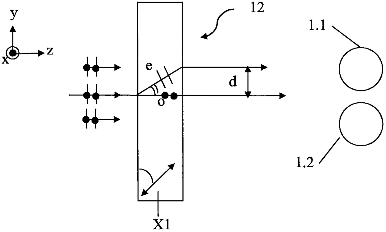
[0060] Specifically, as a possible implementation, see figure 1 as shown, figure 1 The phase conjugate mirror shown in includes a single thermally expanded beam fiber 11, a polarizing beam shifter 12 whose optical axis X1 lies in the plane of the y-z coordinate system, a self-focusing lens 13, and a Faraday rotator with a rotation angle of 45 degrees 14, a dielectric optical film plane reflector 15.

[0061] The thermally expanded beam fiber is a thermally expanded beam fiber (Thermally Expanded Core (TEC) Fiber) that has been heated near the light output end of the fiber. The fundamental mode field diameter of the thermally expanded beam fiber is the mode field of the fiber before thermal expansio...

Embodiment 2

[0070] In Embodiment 2 of the present invention, the polarization beam splitter includes a dual polarization beam shifter and a half-wave plate assembly 22 with a 45-degree angle. For details, see Figure 5 .

[0071] Figure 5 The phase conjugate mirror in contains an optical fiber, a dual-polarization beam shifter and a 45-degree angle half-wave plate assembly 22, a self-focusing lens 13, a 45-degree rotation angle Faraday rotator 14, and a dielectric optical film plane mirror 15.

[0072] see Figure 6 as shown, Figure 5 The dual polarized beam shifter and 45-degree angle half-wave plate assembly 22 are composed of the first polarized beam shifter 3.3, the 45-degree angle half-wave plate 3.4 and the second polarized beam shifter 3.5 in turn, and the first polarized beam The thickness of the shifter 3.3 and the second polarized beam shifter 3.5 are the same, the crystal optical axis X3 of the first polarized beam shifter 3.3 is located in the plane of the y-z coordinate...

Embodiment 3

[0078] In the third embodiment of the present invention, the optical fiber is a thermally expanded beam optical fiber, and the polarization beam splitter includes a dual polarization beam shifter and a 45-degree half-wave plate assembly 22 . That is, the optical phase conjugate mirror in the present embodiment comprises a single thermal beam expander fiber 11, a dual polarization beam shifter and a 45-degree angle half-wave plate assembly 22, a self-focusing lens 13, and a 45-degree rotation angle Faraday rotation Device 14, a dielectric optical thin film plane reflector 15.

[0079] The dual polarization beam shifter and the 45-degree angle half-wave plate assembly 22 are the same as those described in the second embodiment, and will not be repeated in this embodiment.

[0080] In this embodiment, the single heat-expanded optical fiber 11 is a thermally-expanded optical fiber with a mode field diameter of 12 um formed by thermal expansion of an optical fiber with an original ...


PUM


Abstract

The invention discloses an optical-phase conjugation mirror device. The device comprises optical fibers, a polarization spectrometer, a lens, a Faraday rotator and a reflecting mirror; Gaussian divergent light beams emitted from the optical fibers pass through the polarization spectrometer, the lens, the Faraday rotator and the reflecting mirror in sequence, are reflected by the reflecting mirror,then pass through the Faraday rotator, the lens and the polarization spectrometer and are returned to the optical fibers; two light beams divided by the polarization spectrometer deflect and convergethrough the lens, are reflected by the reflecting mirror and then transmitted in the reverse direction of the path of the opposite side, pass through the Faraday rotator again and enter the polarization spectrometer in the reverse direction, and the two light beams are recombined in space and enter the optical fibers. According to the optical-phase conjugation mirror device, nonreciprocal 90-degree angle polarization rotation which is irrelevant to the wavelength and temperature is achieved, the structure is compact, simple and reliable, and meanwhile the optical performance of high extinction ratio, low polarization related loss and low insertion loss is also kept.

Description

[0001] This application claims the priority of the Chinese patent application with the application number 201710180072.2 and the title of the invention "an optical phase conjugate mirror device" submitted to the China Patent Office on March 15, 2017, the entire contents of which are incorporated in this application by reference middle. technical field [0002] The invention relates to the technical field of optical devices with low dependence on light polarization state in the application of light polarization rotation, in particular to an optical phase conjugate mirror device. Background technique [0003] Polarization rotation devices have been used for various purposes in optical systems, especially in applications in fiber optic communications, optical image processing, lasers, and sensors, especially where phase conjugate mirrors are required. Phase conjugate mirrors can eliminate polarization-induced signal fading caused by random birefringence effects in non-PM fibers...

Claims


Application Information

Patent Timeline
Patent Type & Authority Applications(China)
IPC IPC(8): G02F1/095G02B27/28G02B6/02
CPCG02B6/02004G02B27/283G02B27/286G02F1/0955
Inventor 吕婧菲
Owner 吕婧菲
Why Eureka
Try Eureka