Vacuum material taking device for being connected to mechanical arm

A technology of reclaiming device and manipulator, which is applied in the directions of manipulators, conveyor objects, transportation and packaging, etc. It can solve problems such as inapplicability, inefficiency, and complex structure, and achieve stable and reliable movements, concise overall structure, and meet the matching requirements Effect

Active Publication Date: 2018-10-12
CHANGSHU INSTITUTE OF TECHNOLOGY
View PDF19 Cites 0 Cited by
  • Summary
  • Abstract
  • Description
  • Claims
  • Application Information

AI Technical Summary

Problems solved by technology

[0005] Chinese patents CN203143679U (a retrieving device), CN205602253U (a vacuum shaking mask folding machine) and CN206087471U (enhanced shaking suction and feeding mask folding machine) are not limited to the examples of these patents that can absorb more sheets Shaking off is used to ensure that only one sheet is taken at a time, but the shortcoming of this method of taking materials is that in the extraction state, shaking off the whole sheet that has been sucked up is based on the fact that the mask is not afraid of falling damage (that is, the mask will not be damaged when it is shaken off) damage), so these patents are not applicable when the sheet is a product such as a light guide sheet that cannot be dropped
[0006] CN106218956A recommends "a vacuum adsorption rubbing type separation and retrieving mechanism and method", because the patented scheme is designed for the retrieving of specific facial mask sheet products, so the upper and lower parts are attached to each other by rubbing Separation of masks that are together can work, but when facing products such as the aforementioned light guide plates, silicon chips, screen chips, various metal sheets, and PCB boards, etc., then this method (rubbing method) will be due to "Unacclimatized" and unable to work
[0007] CN106494898A provides "a method for taking and extracting sheets for conveying sheets", the structure of which is: including a transverse conveying mechanism, on which a suction sheet lifting mechanism for sucking the end of the sheet is arranged ; Also includes a limiting mechanism for limiting the sheet, lifts one end of the sheet by the suction sheet lifting mechanism, and restricts the other end of the sheet by the limiting mechanism, in the position lifted by the suction sheet lifting mechanism When one end of the sheet is bent and a separation space is formed between the adjacent sheet, the horizontal transfer mechanism drives the suction sheet lifting mechanism to move laterally to extract the sheet (see paragraph 0024 of the patent specification for details), Although this patent solution can realize the technical effect described in paragraph 0016 of its description, it has the following shortcomings: First, because the suction sheet lifting mechanism only absorbs one end of the sheet and makes the end of the sheet elastically bend and deform, the In the process of drawing out the sheet horizontally, there will be dragging friction between the upper layer, that is, the part of the top sheet that has not undergone elastic bending deformation, and the lower sheet, and the dragging friction between the upper and lower adjacent sheets when retrieving the material is called Pull-out friction is extremely unfavorable for delicate products such as light guide plates, silicon wafers, screen sheets, PCB boards, etc., that is, there is a risk of damage to the sheet materials; The synergy with the gas separation mechanism can extract the sheets one by one, so the structure is relatively complicated, which is not conducive to manufacturing, assembly and daily management; thirdly, through the transmission line introduced in the specification of the patent (instruction No. 0025) It can be seen that this patent is not matched with the manipulator, and it cannot be matched with the manipulator, and the retrieving device matched with the manipulator usually requires simple structure, stable and reliable action, light weight, and convenient use and daily maintenance.

Method used


Image

  • Vacuum material taking device for being connected to mechanical arm
  • Vacuum material taking device for being connected to mechanical arm
  • Vacuum material taking device for being connected to mechanical arm

Examples


Embodiment Construction

[0027] In order to understand the technical essence and beneficial effects of the present invention more clearly, the applicant will describe in detail the following examples, but the descriptions of the examples are not intended to limit the solutions of the present invention. Equivalent transformations that are only formal but not substantive should be regarded as the scope of the technical solution of the present invention.

[0028] In the following descriptions, all concepts related to directionality or orientation of up, down, left, right, front and back are based on figure 1 As far as the position state shown is concerned, it cannot be understood as a special limitation on the technical solution provided by the present invention.

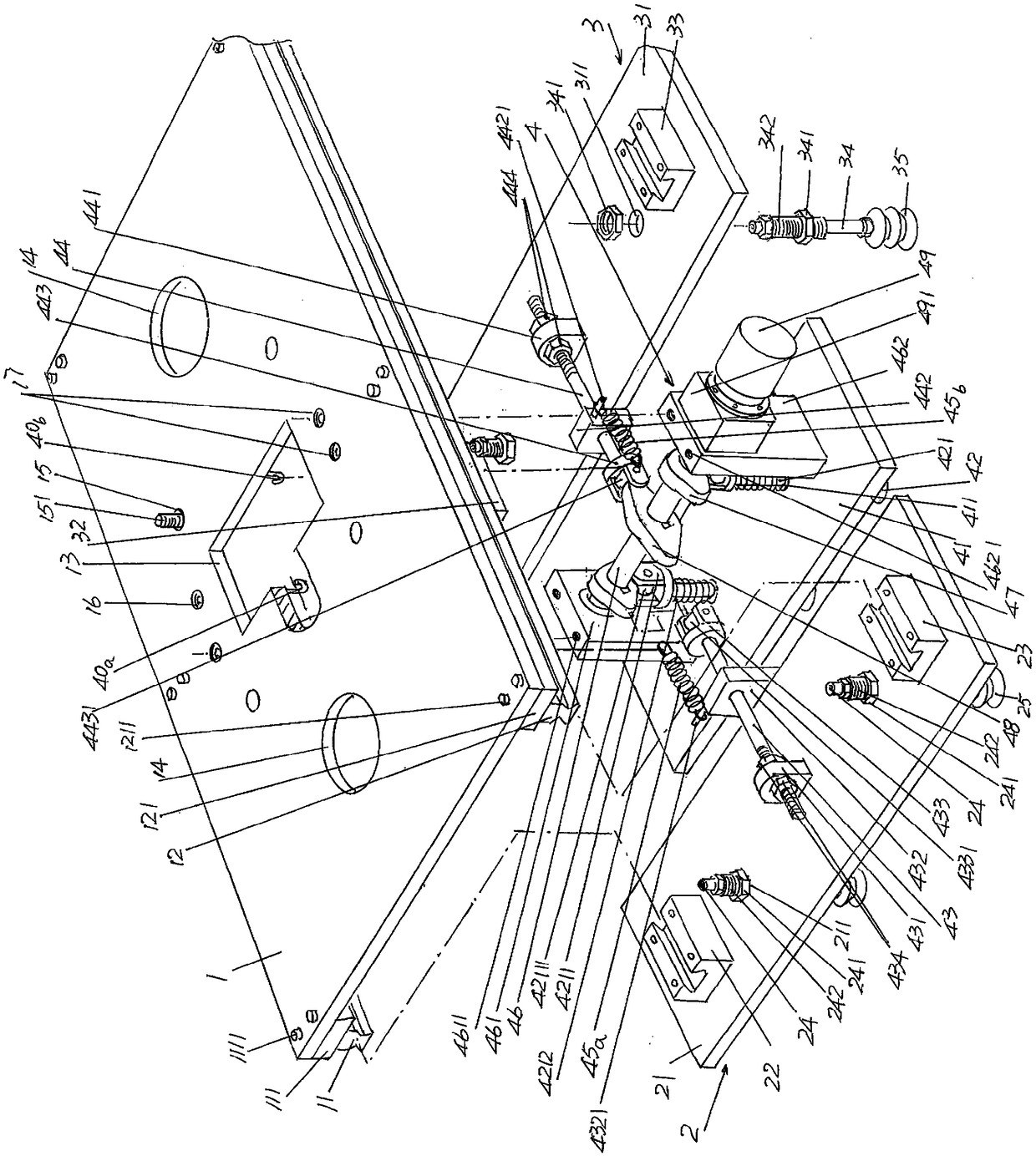
[0029] See figure 1 , shows a manipulator connecting plate 1, a left guide rail 11 is fixed on the edge of the left lower part of the length direction of the manipulator connecting plate 1, that is, the edge on the left side facing downward, ...


PUM


Abstract

The invention discloses a vacuum material taking device for being connected to a mechanical arm. The device comprises a mechanical arm connecting plate, wherein a left guide rail is arranged at the edge part of the lower part of the left side of the mechanical arm connecting plate in the length direction, a right guide rail is arranged at the edge part of the lower part of the right side of the the mechanical arm connecting plate, and a cam receding cavity is formed in the middle of the mechanical arm connecting plate; a sheet material front end sucking mechanism is simultaneously matched withthe front ends of the left guide rail and the right guide rail in a sliding mode at the position, corresponding to the lower part of the front end of the mechanical arm connecting plate; a sheet material rear end sucking mechanism is simultaneously matched with the rear ends of the left guide rail and the right guide in a sliding mode at the position, corresponding to the lower part of the rear end of the mechanical arm connecting plate; and a sliding plate driving mechanism is connected to the sheet material front end sucking mechanism and the sheet material rear end sucking mechanism at the same time corresponding to the position between the sheet material front end sucking mechanism and the sheet material rear end sucking mechanism, and at the position corresponding to the cam receding cavity, the sliding plate driving mechanism is fixed to the side, facing the lower part, of the mechanical arm connecting plate. According to the vacuum material taking device for being connected tothe mechanical arm, only one piece of sheet material is extracted each time; relative friction between the upper adjacent sheet material and the lower adjacent sheet material is avoided in the sheetmaterial extraction process so as to protect the sheet material; and the connection requirements of the device and the mechanical arm can be met.

Description

technical field [0001] The invention belongs to the technical field of automation equipment, and in particular relates to a vacuum reclaiming device for matching with a manipulator. Background technique [0002] The aforementioned vacuum reclaiming device is driven by a manipulator and realizes automatic reclaiming, so as to significantly improve production efficiency and save valuable labor resources. For sheet materials, usually by means of a suction cup, the sheet is sucked by the suction cup under the action of negative pressure, and the sheet is lifted and transferred to a subsequent station such as a transfer station under the action of a robot. Typical but not limited examples of the aforementioned sheet materials are light guide plates, silicon wafers (single crystal silicon or polycrystalline silicon), screen sheets, various metal sheets, PCB boards, etc. The neat and orderly stacked state is led to the station where the vacuum pick-up device is located, so that it...

Claims


Application Information

Patent Timeline
Patent Type & Authority Applications(China)
IPC IPC(8): B25J15/06B65G47/91
CPCB25J15/0616B65G47/91
Inventor 焦洪宇李英张凯左克生林玲胡顺安
Owner CHANGSHU INSTITUTE OF TECHNOLOGY
Why Eureka
Try Eureka