Cathode interface modification method for improving performance of organic electroluminescent device and preparation method of organic electroluminescent device

A technology of cathode interface and modification method, which is applied in the fields of electrical solid device, semiconductor/solid state device manufacturing, electrical components, etc., can solve the high requirements of device processing environment and encapsulation technology, cannot use stable high work function metal, and increase the process process. Difficulty and other problems, to achieve the effect of improving the performance of organic electroluminescent devices, increasing the electron current density, and improving the performance of the device

Active Publication Date: 2018-10-23
SOUTH CHINA UNIV OF TECH
View PDF2 Cites 3 Cited by
  • Summary
  • Abstract
  • Description
  • Claims
  • Application Information

AI Technical Summary

Problems solved by technology

However, such alkali metals and alkaline earth metals with low work functions are easy to react with water and oxygen, and have very high requirements on the processing environment and encapsulation technology of the device, which greatly increases the difficulty of the process
The electron-injecting materials widely used in organic electroluminescent devices are alkali metal halides, alkaline earth metal halides and some metal compounds. This composite cathode can significantly improve electron injection and improve device performance, but this interface The modification method shows strong cathode selectivity, which cannot be applied to some common stable high work function metals, such as gold and silver, which greatly limits its further application

Method used


Image

  • Cathode interface modification method for improving performance of organic electroluminescent device and preparation method of organic electroluminescent device
  • Cathode interface modification method for improving performance of organic electroluminescent device and preparation method of organic electroluminescent device
  • Cathode interface modification method for improving performance of organic electroluminescent device and preparation method of organic electroluminescent device

Examples


Embodiment 1

[0037] The preparation process of the organic electroluminescent device of this embodiment is as follows:

[0038] (1) Cleaning and drying of ITO substrate

[0039] ITO glass square resistance ~ 20Ω / □, size 15mm×15mm square piece. The following steps are used to clean ITO glass: acetone → isopropanol → special detergent for micron semiconductors (a mixed solution of ZT-3 electronic washing liquid and deionized water with a volume ratio of 1:100) → twice deionized water → new Ultrasonic cleaning with isopropanol for 10 minutes each, and drying in a constant temperature oven for two hours for later use. Before use, the ITO clean sheet needs to be processed in the O2plasma system (processing condition parameters: 190V; 120mA; 100Pa; 20min), the purpose is to remove residual organic stains, improve interface contact angle, and improve work function.

[0040] (2) Preparation of hole injection layer

[0041] After the treatment of the ITO glass substrate is completed, spin-coat P...

Embodiment 2

[0057] The cathode interface modification method for improving the performance of organic electroluminescent devices in this embodiment has the same other features as in Embodiment 1, except that in this case, the solution steam treatment time in step C is 30 minutes.

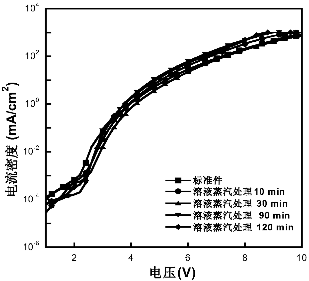
[0058] The current density-voltage curve of the organic light-emitting device of this embodiment is as follows figure 2 As shown (PSVA 30min in the figure), compared with the current density-voltage curve (PSVA in the figure) of the organic light-emitting device whose light-emitting layer has not been treated with solution vapor, the standard part achieves 1000cd / m 2 Under the required voltage of 5.6V and current density of 31.6 mA / cm 2 ,After 10 minutes of solution steam treatment, 1000cd / m 2 Only need a smaller voltage of 5.6V and a smaller current density of 21.7mA / cm 2 .

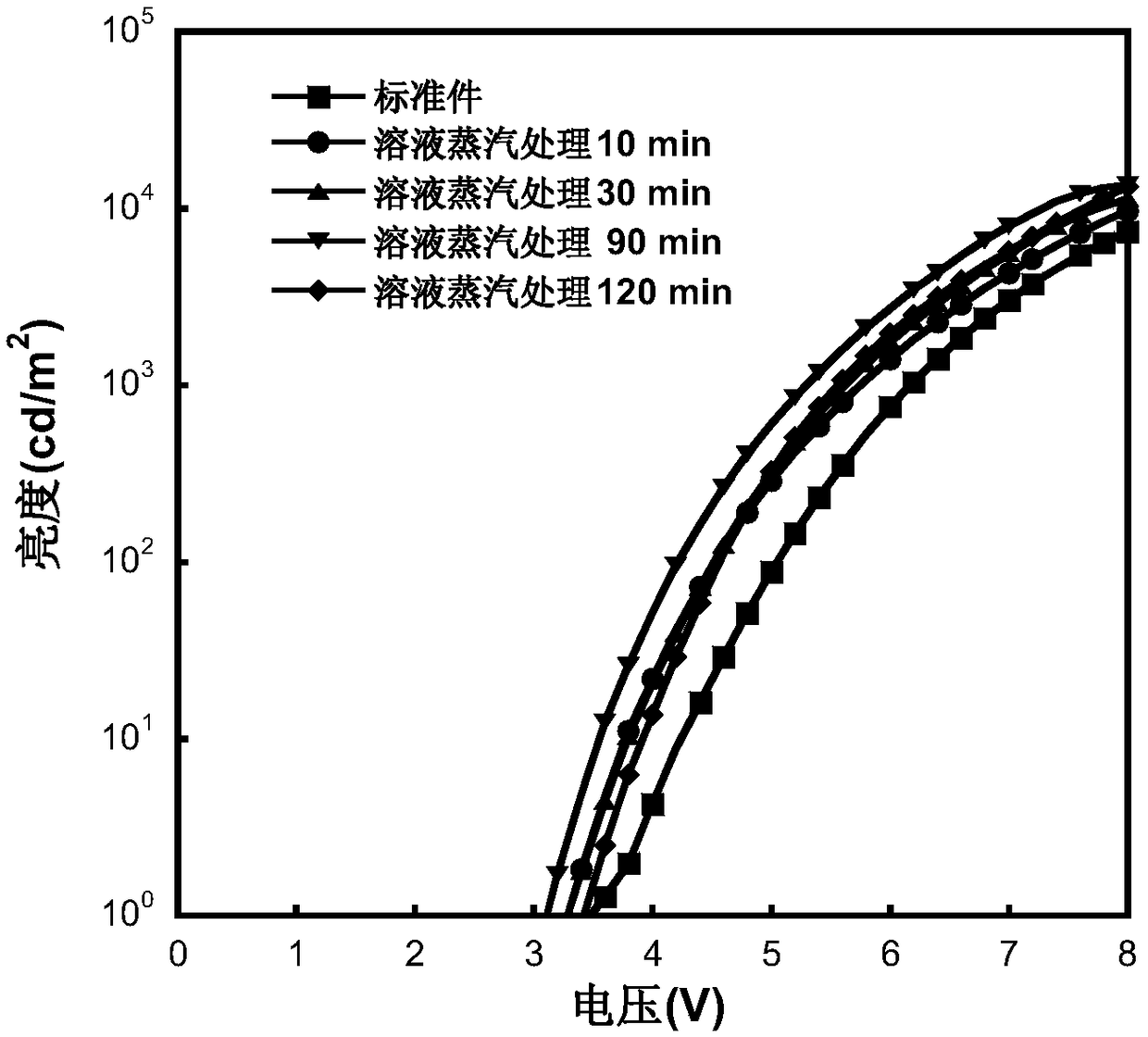
[0059] The voltage-brightness curve of the organic light-emitting device of this embodiment is as follows image 3 As shown (PSVA 3...

Embodiment 3

[0064] The cathode interface modification method for improving the performance of organic electroluminescent devices in this embodiment has the same other features as Case 1, except that the solution steam treatment time in step C in this case is 90 minutes and 120 minutes.

[0065] The current density-voltage curve of the organic light-emitting device of this embodiment is as follows figure 2 As shown (PSVA90min in the figure), compared with the current density-voltage curve (PSVA in the figure) of the organic light-emitting device whose light-emitting layer has not been treated with solution vapor, the standard component achieves 1000cd / m 2 Under the required voltage of 5.6V and current density of 31.6mA / cm 2 ,After 10 minutes of solution steam treatment, 1000cd / m 2 Only need a smaller voltage of 5.0V and a smaller current density of 17.9mA / cm 2 .

[0066] The voltage-brightness curve of the organic light-emitting device of this embodiment is as follows image 3 As show...


PUM


Abstract

The invention discloses a cathode interface modification method for improving the performance of an organic electroluminescent device. Solution steam processing is carried out on a light-emitting layer of an organic electroluminescent device at a room temperature, wherein the steam is generated by a solvent containing a polar group. In addition, the invention also discloses a preparation method ofan organic electroluminescent device. According to the invention, the electron injection barrier is reduced by the solution steam processing; the electron current density is improved; the electron and hole balancing in the organic light-emitting layer is realized; and thus the device performance is improved. The cathode interface modification method and the preparation method of an organic electroluminescent device have characteristics of high solution processibility, simple process, high feasibility, low cost, and high applicability.

Description

technical field [0001] The invention relates to the field of preparation of organic electroluminescent devices, in particular to a cathode interface modification method for improving the performance of organic electroluminescent devices and a preparation method of organic electroluminescent devices. Background technique [0002] Organic Light-Emitting Diode OLED (Organic Light-Emitting Diode) has the characteristics of wide viewing angle, self-illumination, low working voltage, can be used for flexible display, and can realize large-area and low-cost preparation. OLED technology has become a popular emerging flat panel display. The industry has embarked on the road of commercialization and has broad development prospects [0003] Organic electroluminescent diode (OLED) is a double-injection device, electrons and holes are respectively injected into the light-emitting layer from corresponding electrodes to form excitons, and radiate and recombine to emit light. Efficient and...

Claims


Application Information

Patent Timeline
Patent Type & Authority Applications(China)
IPC IPC(8): H01L51/52H01L51/56
CPCH10K71/12H10K50/82H10K71/00
Inventor 王坚寸阳珂宋晨王娟红彭俊彪曹镛
Owner SOUTH CHINA UNIV OF TECH
Why Eureka
Try Eureka