
PEIE intervention standard inverted QLED device and preparation method thereof

A device and standard technology, applied in the field of PEIE intervening standard inverted QLED devices and their preparation

Active Publication Date: 2020-10-23
HENAN UNIVERSITY
View PDF3 Cites 7 Cited by
  • Summary
  • Abstract
  • Description
  • Claims
  • Application Information

AI Technical Summary

Problems solved by technology

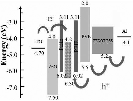
[0003] The purpose of the present invention is to provide a PEIE intervening standard inverted QLED device and its preparation method, aiming to solve the problem of dissolution of quantum dots by the hole transport layer solvent, high hole injection barrier, and excitation of quantum dots caused by the electron transport layer. Sub-quenching to improve the efficiency of flexible devices

Method used


Image

  • PEIE intervention standard inverted QLED device and preparation method thereof
  • PEIE intervention standard inverted QLED device and preparation method thereof
  • PEIE intervention standard inverted QLED device and preparation method thereof

Examples


Embodiment 1

[0042] Using ITO as a substrate, a method for preparing PEIE intervening standard inverted QLED devices,

[0043] Weigh a certain amount of ethoxylated polyethyleneimine, put it in a vacuum drying oven for 24 hours, and prepare it into 0.4 mg / ml ethanol solution and 0.5 mg / ml ethylene glycol methyl ether solution respectively, and place it on a magnetic bar to stir Stir continuously on the mixer for 24 h and wait for the device to be used.

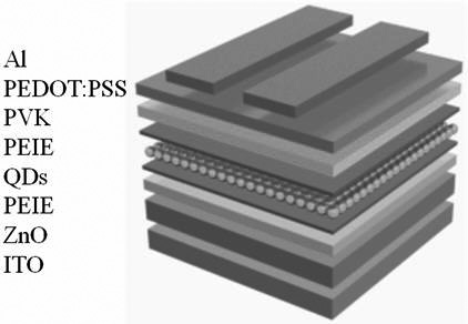
[0044] Such as figure 1 As shown, the specific process is as follows

[0045] a. Spin-coating an electron injection layer on a substrate containing a bottom electrode;

[0046] The substrate containing the bottom electrode of the present invention is an ITO substrate, and the electron injection layer is ZnO, and the ZnO with a particle diameter of 3-4 nm is dissolved in ethanol to prepare a solution with a concentration of 30 mg / ml, 2000 Spin coating at rpm for 45 s, anneal at 80 °C for 30 min, and then anneal at 60 °C for 30 min to obt...

Embodiment 2

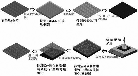
[0056] Through the above method, the manufactured device has high luminous efficiency and excellent electrical transmission performance. On this basis, it was prepared on the single crystal graphene / silver nanowire composite flexible transparent electrode. The preparation method of the flexible electrode is as follows: image 3 As shown, the specific process is as follows:

[0057] a. Transfer of single crystal graphene

[0058] Spin-coat PMMA photoresist at 600 rpm / 6 s and 1500 rpm / 15 s on the surface of copper foil (copper foil thickness 0.5 μm) grown with 0.5 nm-1 nm thick graphene, and anneal at 180 °C for 5 min; then PMMA / Graphene / copper foil was placed in FeCl with a concentration of 2 mol / mL 3 solution, remove the copper foil by etching; then transfer the PMMA / graphene to concentrated hydrochloric acid: deionized water = 1:1 solution for immersion for 30 min, concentrated hydrochloric acid is 36-38wt%; continue to transfer the film cycle to the washed three times ...


PUM

PropertyMeasurementUnit
Thicknessaaaaaaaaaa
Thicknessaaaaaaaaaa
Thicknessaaaaaaaaaa

Abstract

The invention discloses a PEIE intervention standard inverted QLED device and a preparation method thereof. The preparation method comprises the following steps: (1) depositing a ZnO electron injection layer on a flexible substrate; (2) spin-coating a PEIE solution on the ZnO electron injection layer to prepare an interface modification layer A; (3) depositing a quantum dot light-emitting layer onthe interface modification layer A, wherein the quantum dot light-emitting layer is made of ZnCdSeS / ZnS green light quantum dots; (4) depositing a PEIE solution on the quantum dot light-emitting layer to prepare an interface modification layer B; (5) depositing a hole transport layer and a hole injection layer on the interface modification layer B, wherein the hole transport layer is one or moreof PVK, TFB, poly-TPD, TCTA and CBP, and the hole injection layer is PEDOT: PSS; and (6) evaporating a top electrode, wherein the top electrode is an Al, Ag, Cu, Au or alloy electrode, and after evaporation of the device is completed, packaging the device.

Description

technical field [0001] The invention belongs to the technical field of light emitting diodes, and in particular relates to a PEIE intervening standard inverted QLED device and a preparation method thereof. Background technique [0002] Compared with traditional organic light-emitting diodes (Organic Light-Emitting Diodes, OLED), quantum dot light-emitting diodes (Quantum Dot Light-Emitting Diodes, referred to as QLED) have high color purity, high material stability, and the luminous color varies with the size of quantum dots. The advantages of continuous tunability and solution processing make QLED the best candidate for low-cost development, large-area fabrication, and flexible displays. QLED is one of the high-tech products that is most likely to replace OLED and start the industrial revolution in the display field. At present, although QLED has been initially applied in the display field, such as QLED TV produced by Samsung, etc. However, QLED with an inverted structure ...

Claims


Application Information

Patent Timeline
IPC IPC(8): H01L51/56H01L51/50H01L51/54
CPCH10K85/111H10K50/115H10K71/00
Inventor 杜祖亮王书杰张梦华王啊强方岩
Owner HENAN UNIVERSITY
Learn More