Welding groove heat treatment jet burning system

A welding port and burner technology, applied in heat treatment furnaces, heat treatment equipment, furnaces, etc., can solve the problems of large time span, low flexibility, secondary residual stress of component cooling speed, etc., to avoid flame concentration and overcome welding. Defects, effects of avoiding undesirable effects

Pending Publication Date: 2018-10-26
GUILIN UNIV OF ELECTRONIC TECH
View PDF0 Cites 0 Cited by
  • Summary
  • Abstract
  • Description
  • Claims
  • Application Information

AI Technical Summary

Problems solved by technology

The second is the local plastic deformation caused by the uneven volume expansion caused by the phase transition.
[0005] First: The flame of the existing burner is highly concentrated and the temperature is high. In terms of the characteristics of thermal stress relief, simply heating and remelting a certain welding joint cannot achieve the desired effect, and even the components will be affected by the cooling speed. And cause secondary residual stress;
[0006] Second: the limitations are large, some fixed large parts cannot be processed, the time span is large, and the flexibility is low;
[0007] Third: At present, the current situation at home and abroad basically adopts the method of eliminatin

Method used


Image

  • Welding groove heat treatment jet burning system
  • Welding groove heat treatment jet burning system
  • Welding groove heat treatment jet burning system

Examples


Example Embodiment

[0028] The present invention will be further described below in conjunction with the drawings and embodiments.

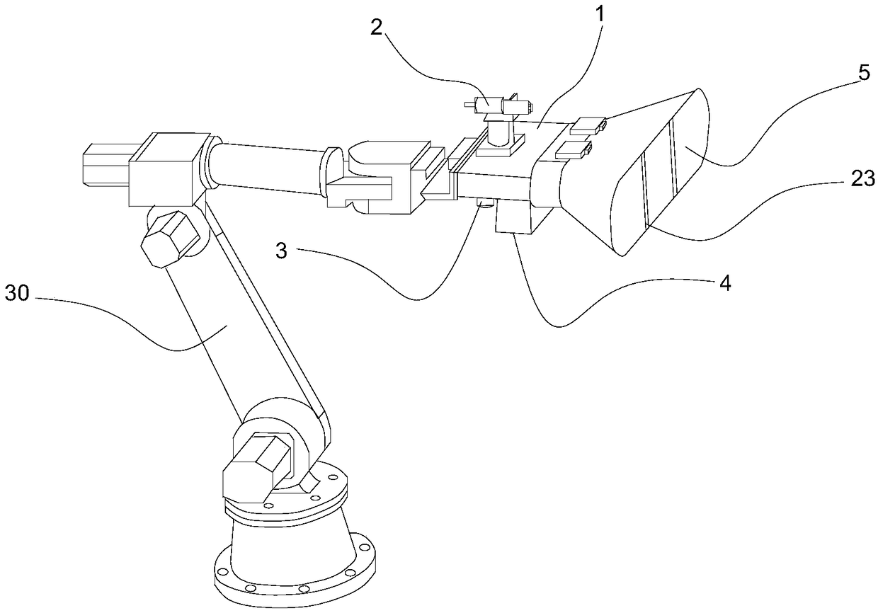
[0029] Such as Figure 1 to Figure 6 As shown, the welding port heat treatment and combustion system of the present invention includes a burner 1, an infrared temperature measuring device 2 is arranged above the burner 1, and a gas input port 3 is arranged below the burner 1. Support gas inlet 4;

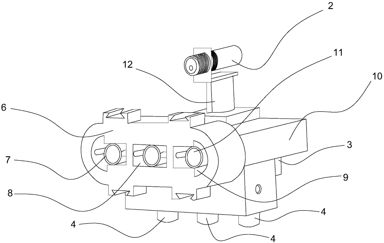
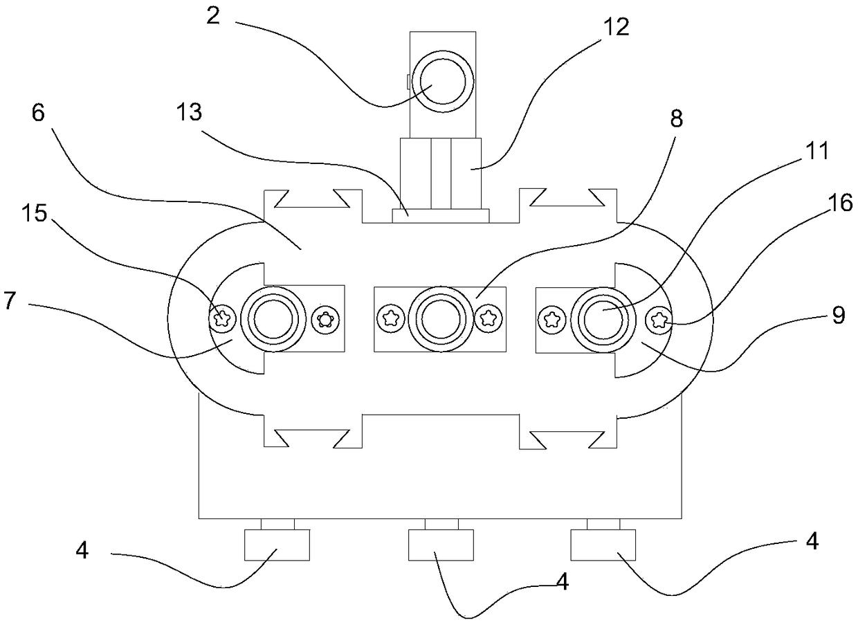
[0030] The burner 1 includes a protective shell 10 and a flame spray head shell 6 arranged at one end of the protective shell 10; the flame spray head shell 6 is provided with three flame spray chambers, in turn are a heating flame spray chamber 7, a constant temperature flame spray chamber 8. , Cooling fire spray chamber 9; and each fire spray chamber is provided with a spray gun 11;

[0031] Both sides of the spray gun 11 are respectively provided with an ignition needle 15 and an induction needle 16; the spray gun 11 is provided with a shuttle 22 smaller than the diameter o...


PUM


Abstract

The invention discloses a welding groove heat treatment jet burning system which is easy to operate, low in manufacturing cost, convenient to use and high in practicability. The welding groove heat treatment jet burning system comprises a jet burner and a control system based on STM32. An infrared temperature measuring device is arranged on the upper portion of the jet burner. A fuel gas input port and a combustion-supporting gas inlet are formed in the lower portion of the jet burner. The jet burner comprises a protection outer shell and a fire-jet head outer shell arranged at one end of theprotection outer shell. Three fire jet cavities are formed in the fire-jet head outer shell, namely the temperature increasing fire jet cavity, the temperature constant fire jet cavity and the temperature decreasing fire jet cavity which are arranged in sequence. A spray gun is arranged in each fire jet cavity. A shuttle with the diameter between smaller than that of a nozzle is arranged in each spray gun. A flow control device is arranged at the combustion-supporting gas inlet. Another flow control device is further arranged at the fuel gas input port. The infrared temperature measuring device and the flow control devices are electrically connected with the control system based on STM32. By adopting the jet burner and the control system based on STM32, thermal stress relieving of weldinggrooves can be achieved, and welding defects are eliminated.

Description

technical field [0001] The invention relates to the field of mechanical equipment automation, in particular to a combustion system for heat treatment of welding joints. Background technique [0002] It is well known that the residual stress caused by the uneven heating temperature of the object during processing mainly has the following two reasons: the first is the local thermoplastic deformation caused by the uneven temperature. The second is the local plastic deformation caused by the uneven volume expansion caused by the phase transition. The residual stress caused by component dimensional tolerances is often caused by fit problems. For example, when the hull sections are docked, the butt steel plates must be pulled together. These structures are pulled together by external tension. After the external force is removed, the entire system There is a residual stress. The influence of residual stress plays a negative role in most cases; such as reducing the strength of the...

Claims


Application Information

Patent Timeline
IPC IPC(8): C21D9/50C21D1/52
CPCC21D9/50C21D1/52
Inventor 甘勇张秋锋朱卫强蒙旭张伟杰
Owner GUILIN UNIV OF ELECTRONIC TECH
Why Eureka
Try Eureka