
Treatment device for polycrystalline silicon reduction tail gases

A processing device and polysilicon technology, applied in gas processing, combined device, halogenated silane, etc., can solve the problems of system shutdown, large number of equipment, wear and tear, etc., to reduce processing energy consumption, reduce investment quota, and achieve high economic benefits. Effect

Active Publication Date: 2018-11-02
新疆新特晶体硅高科技有限公司
View PDF5 Cites 6 Cited by
  • Summary
  • Abstract
  • Description
  • Claims
  • Application Information

AI Technical Summary

Problems solved by technology

[0006] One is that it is impossible to effectively remove the silicon powder brought into the CDI unit through the tail gas after reduction production
The silicon powder brought in will block and wear the tower and pump of the CDI device, resulting in equipment damage or system shutdown, and will affect the downstream process
[0007] Second, the energy consumption of CDI devices is relatively high
[0008] The third is that the system is huge, the equipment is huge, and it is difficult to overhaul and maintain
The CDI device of a 10,000-ton polysilicon enterprise covers an area of ​​12,000m 2 Above, the investment reached more than 200 million yuan, and there were as many as 200 sets of various towers, pumps, heat exchangers, compressors, refrigerators, tanks, tanks, etc., and the damage of each set of equipment may cause local or full system parking
[0009] The above reasons lead to rising costs and frequent system failures in the polysilicon production process, resulting in a decline in the competitiveness of enterprises

Method used


Image

  • Treatment device for polycrystalline silicon reduction tail gases
  • Treatment device for polycrystalline silicon reduction tail gases
  • Treatment device for polycrystalline silicon reduction tail gases

Examples


Embodiment Construction

[0036] In order to enable those skilled in the art to better understand the technical solutions of the present invention, the present invention will be further described in detail below in conjunction with the accompanying drawings and embodiments.

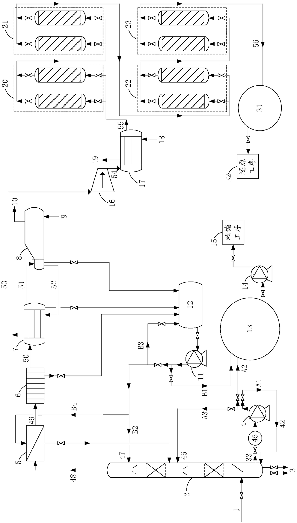
[0037] An embodiment of the present invention provides a treatment device for polysilicon reduction tail gas, which mainly relates to the research of polysilicon production technology and the application of the device in polysilicon production. The temperature of the reduction tail gas is about 130°C and the pressure is 0.45MPa, which includes a mixture of hydrogen, chlorosilane and a small amount of silicon powder. The chlorosilane includes trichlorosilane, silicon tetrachloride and dichlorodihydrosilane . Wherein, the volume percentage of silicon powder in the reduction tail gas is only 0.1%, although the proportion is small, it has a greater impact on the polysilicon production process and should be removed; of course, the mixe...


PUM


Abstract

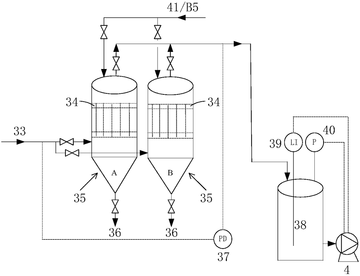
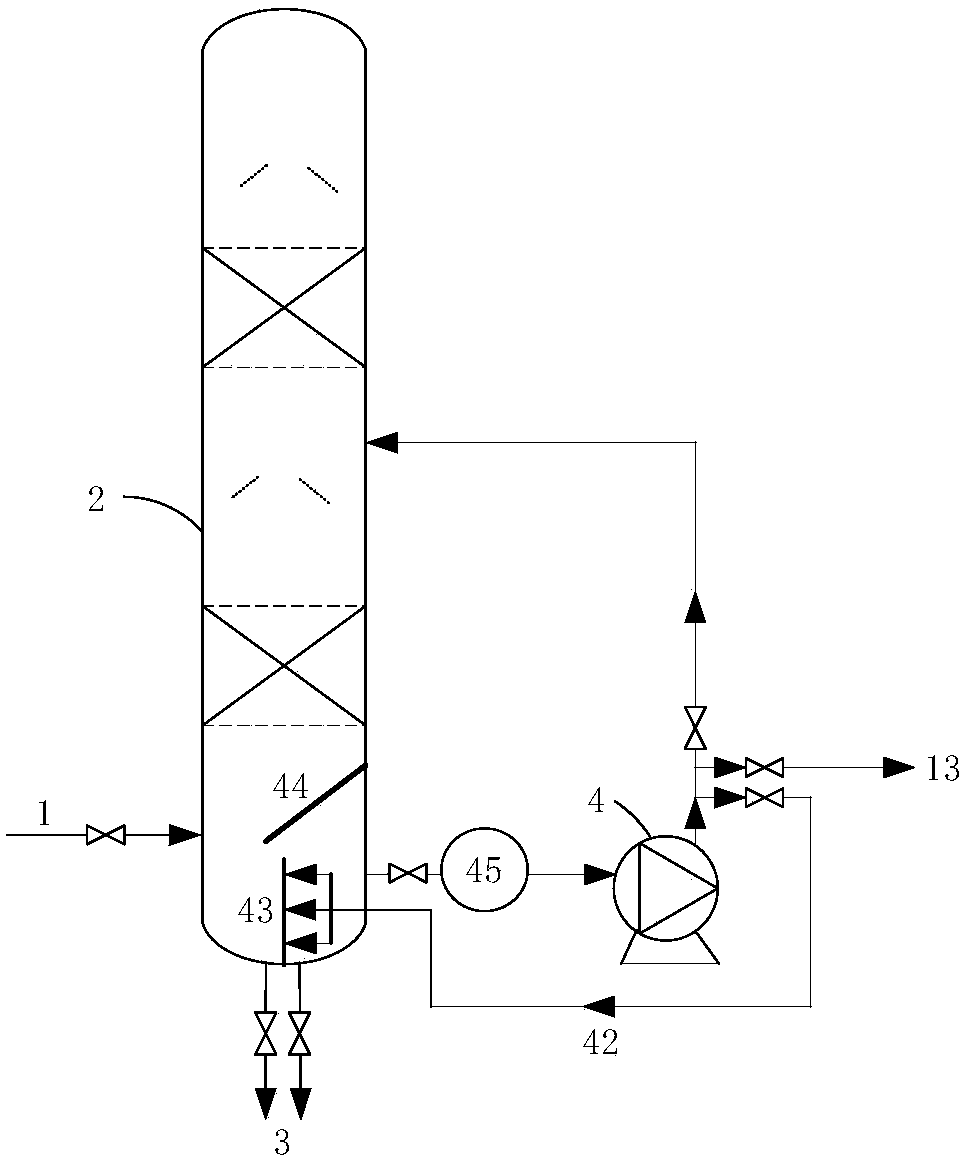
The invention provides a treatment device for polycrystalline silicon reduction tail gases. The treatment device comprises a scrubbing tower, a circulating pump protection unit, a scrubbing tower circulating pump, a dust removal unit, a multistage cooling unit and a multistage activated carbon adsorption unit, wherein the scrubbing tower is used for rinsing reduction tail gases, outputting siliconpowder-containing chlorosilane liquid from the column bottom and outputting non-condensable gas from the tower top; the circulating pump protection unit is used for removing silicon powder and impurities in the silicon powder-containing chlorosilane liquid and outputting chlorosilane liquid; the scrubbing tower circulating pump is used for pressurizing the chlorosilane liquid and feeding the liquid into the scrubbing tower to participate in rinsing; the dust removal unit is used for removing silicon powder in the non-condensable gas so as to obtain non-condensable gas subjected to dust removal; the multistage cooling unit is used for sequentially performing multistage cooling on the non-condensable gas subjected to dust removal, totally condensing the chlorosilane therein, feeding the chlorosilane into a chlorosilane condensate collection tank, and outputting impurity-containing hydrogen; the multistage activated carbon adsorption unit is used for performing multistage adsorption on the impurity-containing hydrogen output by the multistage cooling unit in sequence, obtaining pure hydrogen and feeding the hydrogen into a hydrogen buffer tank. According to the treatment device disclosed by the invention, the silicon powder in the reduction tail gases can be effectively reduced.

Description

technical field [0001] The invention relates to the technical field of polysilicon production, in particular to a treatment device for polysilicon reduction tail gas. Background technique [0002] Polysilicon is a key raw material used in integrated circuits and photovoltaic power generation, and is a necessary raw material for the country's new energy development. In the current era of increasing shortage of fossil energy, the rise of new energy has become an inevitable trend. [0003] In the polysilicon production process in my country, 90% of the polysilicon production enterprises adopt the improved Siemens method polysilicon production process for polysilicon production, and at the same time use the CDI device (that is, the tail gas dry recovery device) to treat the tail gas generated by the reduction device (that is, the reduction tail gas) For recycling. Specifically, the hydrogen and chlorosilane in the reduction tail gas are separated and treated, and then the impur...

Claims


Application Information

Patent Timeline
IPC IPC(8): C01B3/50C01B33/107C01B33/035B01D50/00B01D53/00B01D53/02
CPCB01D53/002B01D53/02C01B3/50C01B33/035C01B33/1071C01B2203/042C01B2203/0415B01D2258/02B01D2257/204B01D2256/16B01D50/60
Inventor 陈世涛王文
Owner 新疆新特晶体硅高科技有限公司
Learn More