Transceiver networking radar autonomous time synchronizing system based on pseudo random coding signal and method thereof

A time synchronization system and pseudo-random coding technology, applied in the radar field, can solve the problems of being easily affected by Doppler, the synchronization accuracy is reduced, and the taming time is long, so as to reduce the cost of transceiver time synchronization, high synchronization accuracy, and anti-interference Good results

Active Publication Date: 2018-11-02
SPACE STAR TECH CO LTD
View PDF10 Cites 11 Cited by
  • Summary
  • Abstract
  • Description
  • Claims
  • Application Information

AI Technical Summary

Problems solved by technology

[0004] At present, there are mainly four time synchronization schemes for transceiver networking radars: first, when the conditions are met, using optical fiber or coaxial cable for time synchronization is difficult to meet the requirements of relatively moving transceiver networking radars; second, using Synchronization with a high-stable atomic clock can achieve better synchronization, but it is expensive; third, using GPS to tame the high-stable crysta

Method used


Image

  • Transceiver networking radar autonomous time synchronizing system based on pseudo random coding signal and method thereof
  • Transceiver networking radar autonomous time synchronizing system based on pseudo random coding signal and method thereof
  • Transceiver networking radar autonomous time synchronizing system based on pseudo random coding signal and method thereof

Examples


Embodiment Construction

[0061] Hereinafter, the present invention will be described in detail based on the drawings.

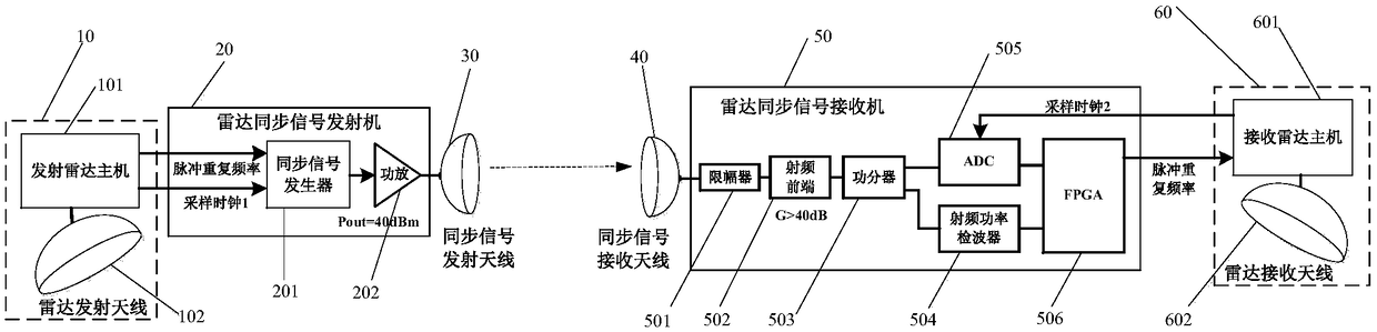
[0062] Such as figure 1 As shown, the present invention has designed a kind of autonomous time synchronization system of transceiver networking radar based on pseudo-random coding signal, and the system mainly includes:

[0063] The radar transmitting host and the radar antenna 10 are used to generate and transmit high-power radar signals to the target detection area, and generate sampling clock signals and pulse repetition frequency signals required by the radar transmitting system;

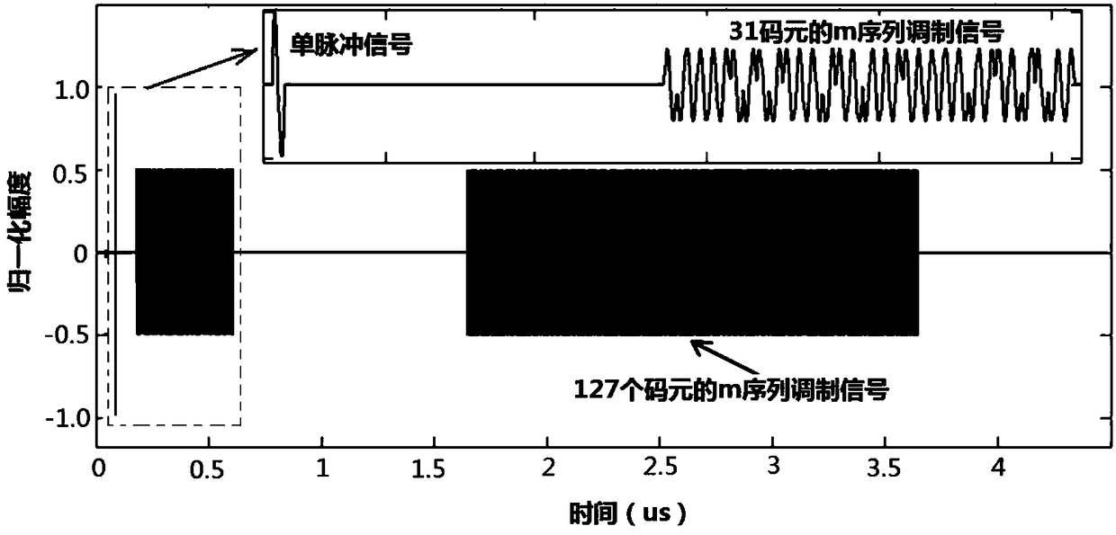
[0064] The radar synchronous signal transmitter 20 is used to generate radar synchronous signals according to the clock signal and the pulse repetition frequency signal and perform power amplification, wherein the radar synchronous signals include single pulse signals, short code element m-sequence modulation signals, and long code element m-sequence modulation signals ;

[0065] A synchronous signal...


PUM


Abstract

The invention provides a transceiver networking radar autonomous time synchronizing system based on a pseudo random coding signal and a method thereof. The method comprises the steps of generating a sampling clock signal and a pulse repetition frequency signal which are required for radar transmission, thereby generating a radar synchronization signal, performing power amplification and radiating,wherein the radar synchronization signal comprises a monopulse signal, a short-code-element m-sequence modulating signal and a long-code-element m-sequence modulating signal; performing preprocessingand sampling on the received radar synchronizing signal, performing pulse compression processing on the direct wave signals of the short-code-element m-sequence modulating signal and the long-code-element m-sequence modulating signal, and calculating a highest value of a respective pulse response function; and calculating the time interval of the highest value of two or more adjacent long-code-element pulse response functions, and using the reciprocal of the time interval as the pulse repetition rate of the radar transmitting signal. The transceiver networking radar autonomous time synchronizing system and the method thereof can realize nanosecond-grade synchronizing precision and furthermore have advantages of low cost, low power consumption, high signal-to-noise ratio, high interferenceresistance, simple system structure, etc.

Description

technical field [0001] The invention belongs to the technical field of radar, and relates to an autonomous time synchronization system and method for a transceiver networking radar based on a pseudo-random coded signal. Background technique [0002] In recent years, the transceiver network radar technology has attracted much attention in the scientific and engineering circles, especially in the fields of space-based transceiver network imaging radar earth observation, distributed radar multi-view imaging and other fields with great application value. The transceiver networked imaging radar has the advantages of high-resolution wide-band imaging detection without blind spots, and can obtain the scattering characteristics of ground targets in multiple directions, providing rich information for later target characteristic inversion; at the same time, the transceiver networked radar can also be used for For the detection of stealth targets, the detection performance of stealth t...

Claims


Application Information

Patent Timeline
IPC IPC(8): G01S7/42
CPCG01S7/42
Inventor 夏正欢李科贺广均赵志龙冯鹏铭郭宇华刘敦歌王进郝研陈昊
Owner SPACE STAR TECH CO LTD
Why Eureka
Try Eureka