Novel active carbon analysis tower and active carbon analysis process

A technology of activated carbon and analytical tower, applied in the field of sintering flue gas treatment, can solve the problems of high moisture content, high heat and high temperature

Pending Publication Date: 2018-11-06
ZHONGYE-CHANGTIAN INT ENG CO LTD
View PDF0 Cites 7 Cited by
  • Summary
  • Abstract
  • Description
  • Claims
  • Application Information

AI Technical Summary

Problems solved by technology

It can be seen that SRG gas has a large water content, high temperature, and high-temperature and high-corrosion properties. Therefore, the acid production process is made of glass fiber reinforced plastic. The glass fiber reinforced plastic material has high temperature requirements, and generally requires operation below 100 ° C. It will cause the following adverse effects: (1) SRG gas has high corrosion characteristics, which requires the acid purification device to be made of glass fiber reinforced plastics, while water has a large spe

Method used


Image

  • Novel active carbon analysis tower and active carbon analysis process
  • Novel active carbon analysis tower and active carbon analysis process
  • Novel active carbon analysis tower and active carbon analysis process

Examples


Embodiment 1

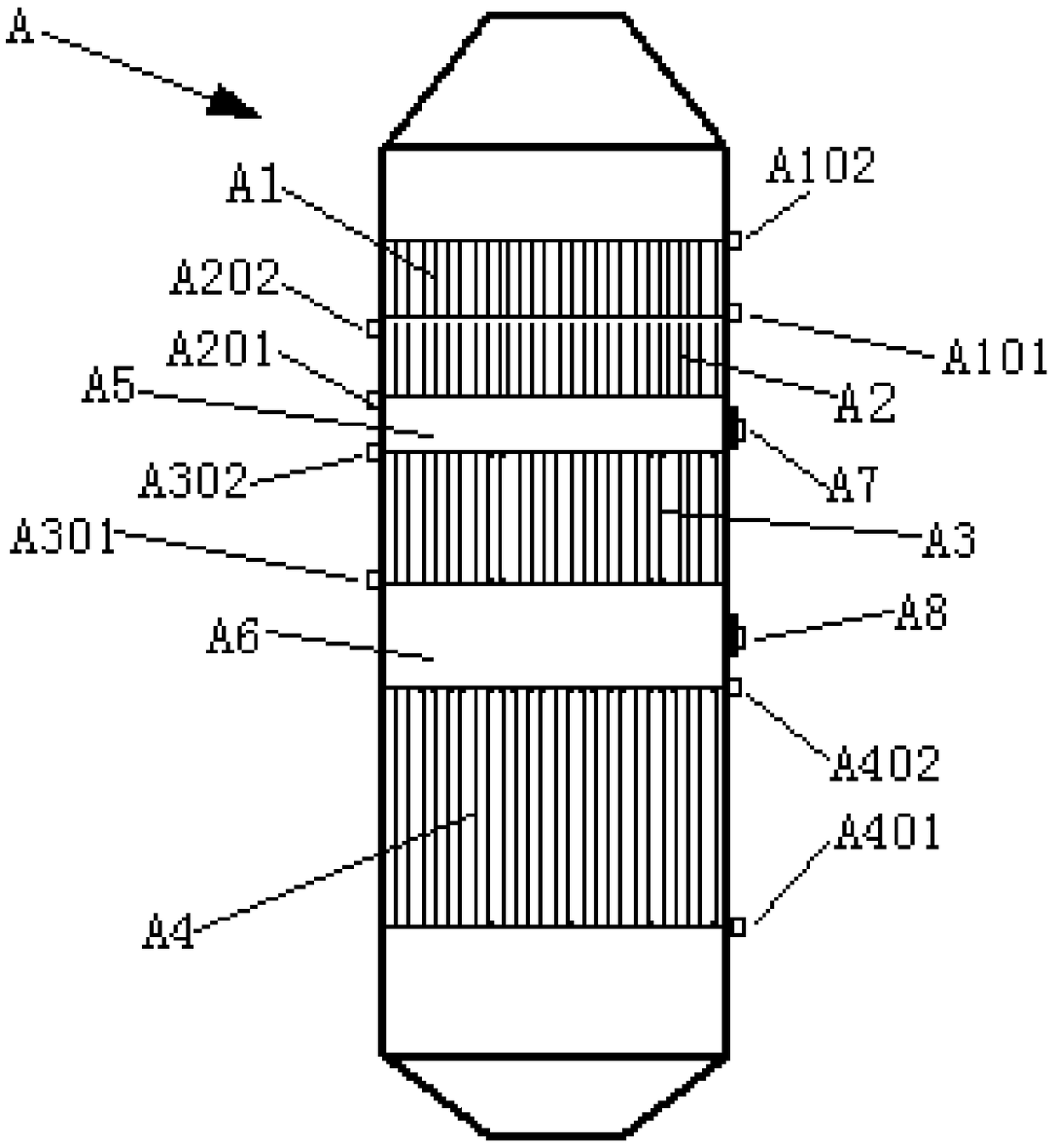
[0089] Such as figure 1 As shown, a new type of activated carbon desorption tower, the activated carbon desorption tower A includes preheating zone A1, water vapor decomposition zone A2, pollutant decomposition zone A3, cooling zone A4, first transition section A5 and the second Two transition section A6. The lower part of the preheating zone A1 is provided with a preheating zone gas inlet A101 and a preheating zone gas outlet A102. The lower part of the water vapor decomposition zone A2 is provided with a water vapor decomposition zone gas inlet A201 and a water vapor decomposition zone gas outlet A202. The lower part of the pollutant decomposition zone A3 is provided with a gas inlet A301 for the pollutant decomposition zone and a gas outlet A302 for the pollutant decomposition zone. The lower part of the cooling zone A4 is provided with a cooling zone gas inlet A401 and a cooling zone gas outlet A402. The first transition section A5 is between the water vapor decompositi...

Embodiment 2

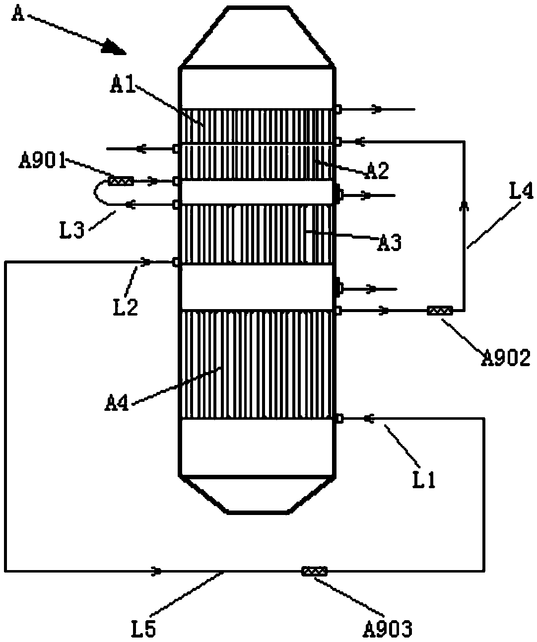
[0091] Such as figure 2 As shown, Example 1 is repeated, except that the gas outlet A302 of the pollutant decomposition zone is connected to the gas inlet A101 of the preheating zone through the first delivery pipeline L3. The gas outlet A402 of the cooling zone is connected to the gas inlet A101 of the preheating zone through the second delivery pipe L4. The gas outlet A202 of the water vapor decomposition zone is connected to the gas inlet A101 of the preheating zone through the third delivery pipeline L5.

Embodiment 3

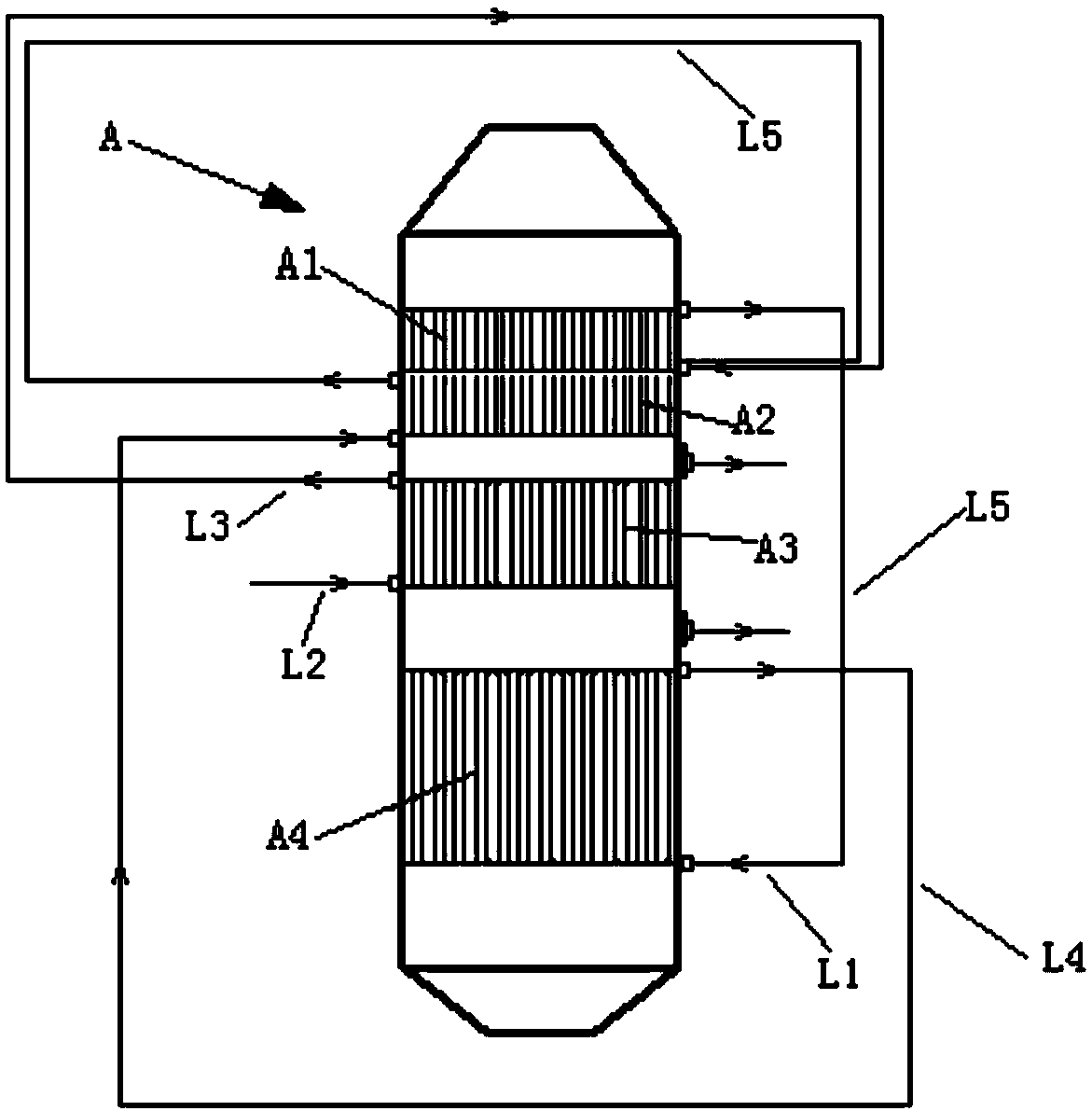
[0093] Repeat Example 2, except that the gas outlet A402 of the cooling zone is connected to the gas inlet A201 of the water vapor decomposition zone through the second delivery pipeline L4. The gas outlet A202 of the water vapor decomposition zone is connected to the gas inlet A401 of the cooling zone through a third delivery pipeline L5.


PUM


Abstract

The invention relates to a novel active carbon analysis tower and an active carbon analysis process. According to different decomposition temperatures of pollutants adsorbed by active carbon, the active carbon analysis tower (A) is provided with a preheating region (A1), a water vapor decomposition region (A2), a pollutant decomposition region (A3), a cooling region (A4), a first transitional section (A5) and a second transitional section (A6) from top to bottom, wherein a water vapor outlet (A7) is formed in the side wall of the first transitional section (A5); an SRG gas outlet (A8) is formed in the side wall of the second transitional section (A6). Water in the active carbon is separated in advance by a step-by-step heating method, so as to reduce the moisture content in SRG gas to create good conditions for normal operation of acid preparation and wastewater treatment procedures at the downstream.

Description

technical field [0001] The invention relates to an activated carbon thermal analysis tower, in particular to an analysis tower device capable of removing moisture in activated carbon, and belongs to the field of sintering flue gas treatment. Background technique [0002] For industrial flue gas, especially sintering machine flue gas in the iron and steel industry, it is ideal to use desulfurization and denitrification devices and processes including activated carbon adsorption towers and desorption towers. In the desulfurization and denitrification devices including activated carbon adsorption tower and desorption tower (or regeneration tower), the activated carbon adsorption tower is used for adsorption of sulfur oxides, nitrogen, and Pollutants including oxides and dioxins, while the desorption tower is used for thermal regeneration of activated carbon. [0003] Activated carbon desulfurization has the advantages of high desulfurization rate, simultaneous denitrification,...

Claims


Application Information

Patent Timeline
IPC IPC(8): B01J20/34B01J20/20B01D53/02
CPCB01D53/02B01J20/20B01J20/3416B01J20/3483B01D2253/102
Inventor 李俊杰魏进超刘昌齐
Owner ZHONGYE-CHANGTIAN INT ENG CO LTD
Why Eureka
Try Eureka