
Tail gas pipe cutting device for vehicle manufacturing

A technology for automobile manufacturing and cutting devices, which is applied in the direction of manufacturing tools, auxiliary devices, welding/cutting auxiliary equipment, etc. It can solve problems such as inaccurate angles, difficult control, troublesome operation, etc., to ensure cutting quality and improve work efficiency , the effect of improving efficiency

Pending Publication Date: 2018-11-06
WENZHOU UNIV OUJIANG COLLEGE
View PDF2 Cites 9 Cited by
  • Summary
  • Abstract
  • Description
  • Claims
  • Application Information

AI Technical Summary

Problems solved by technology

[0007] It is more difficult for the cutting machine to cut the exhaust pipe of the car, and the round exhaust pipe is easy to slip. It needs to be controlled manually before cutting, and the operation is more troublesome.
[0008] 2. The existing exhaust pipe cutting device for automobile manufacturing, and because the exhaust pipe needs to be cut at different angles, the control is difficult, it is not convenient for the cutting machine to cut, and the angle after cutting is not accurate
[0009] 3. The existing exhaust pipe cutting device for automobile manufacturing, during the cutting work, because the heat of the high-temperature plasma arc contacts the workpiece to achieve the purpose of cutting, resulting in dust adhered to the surface of the workpiece, which cannot be cleaned in time, which will affect the follow-up cutting work
[0010] 4. The existing exhaust pipe cutting device for automobile manufacturing is not flexible enough to adjust the height of the dust suction pipe, and the effect of dust suction will be reduced, and it will be sucked when installing and disassembling the workpiece. The limitation of the dust pipe is easy to knock down, which makes it inconvenient to install and disassemble the workpiece

Method used


Image

  • Tail gas pipe cutting device for vehicle manufacturing
  • Tail gas pipe cutting device for vehicle manufacturing
  • Tail gas pipe cutting device for vehicle manufacturing

Examples


Embodiment Construction

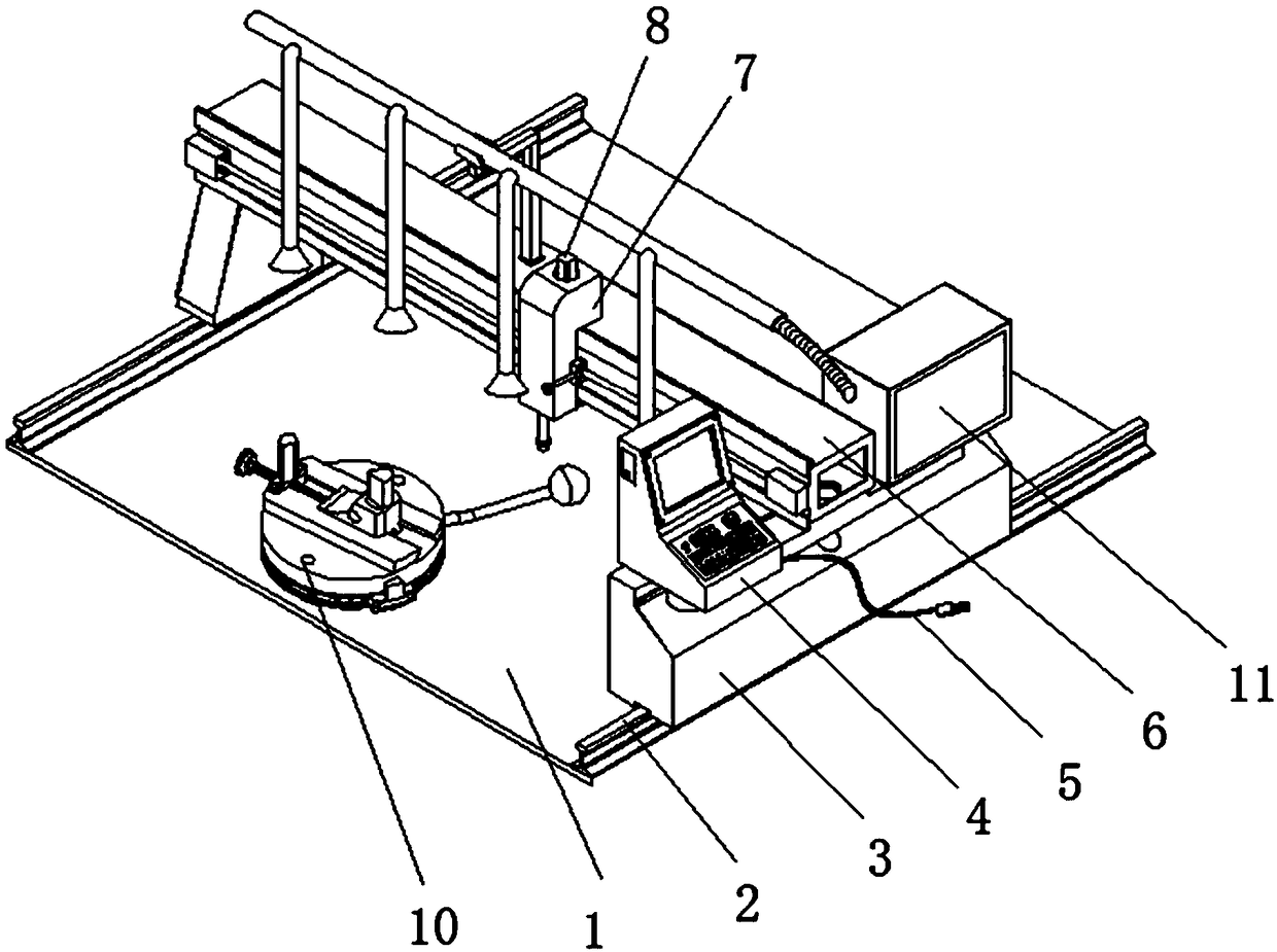
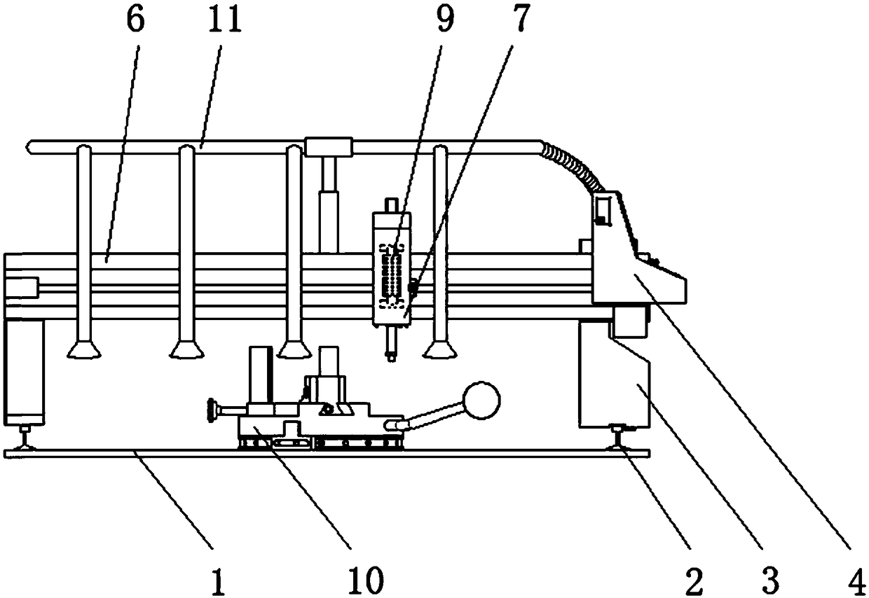
[0058] The following will be combined with Figure 1-9 The present invention is described in detail, and the technical solutions in the embodiments of the present invention are clearly and completely described. Apparently, the described embodiments are only some of the embodiments of the present invention, not all of them. Based on the embodiments of the present invention, all other embodiments obtained by persons of ordinary skill in the art without making creative efforts belong to the protection scope of the present invention.

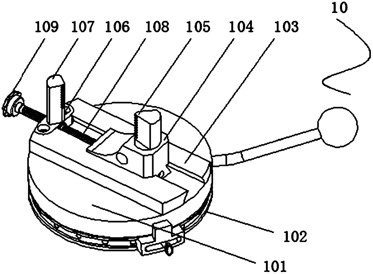
[0059] The present invention provides a kind of exhaust pipe cutting device for automobile manufacturing through improvement, including workbench 1, first slide rail 2, support platform 3, control panel 4, power cord 5, beam 6, machine head 7, motor 8, The electrode rod 9, the clamping device 10 and the dust collection device 11, the bottom of the first slide rail 2 are welded on the left and right sides of the top of the workbench 1, and the suppor...


PUM

PropertyMeasurementUnit
Lengthaaaaaaaaaa

Abstract

The invention discloses a tail gas pipe cutting device for vehicle manufacturing. The device comprises a workbench, a first slide rail, a supporting table, a control panel, a power line, a cross beam,a machine head, a motor, an electrode bar, a clamping device and a dust sucking device; the supporting table is arranged at the upper end of the first slide rail and is in sliding connection with theouter side of the first slide rail; the front and back ends of the bottom of the control panel are fixed to the front side of the top end of the supporting table through screws; after a hand wheel isrotated, the distance between a left clamping rod and a right clamping rod changes, a tail gas pipe is put between the left clamping rod and the right clamping rod, then the left clamping rod and theright clamping rod clamp and position the tail gas pipe after the hand wheel is rotated reversely, the shifting condition is avoided during cutting, cutting is more convenient, and the work efficiency is improved. By arranging a rotary mechanism, after the tail gas pipe is fixed on a positioning board, a rocker can be pulled to change the angle of a rotary disc and the positioning board, then theangle of the tail gas pipe is adjusted accordingly, the tail gas pipe can be cut with the accurate angle, and the cutting quality is ensured.

Description

technical field [0001] The invention relates to the related field of exhaust pipe cutting devices, in particular to an exhaust pipe cutting device for automobile manufacturing. Background technique [0002] The exhaust pipe is a part of the engine exhaust system, and the exhaust pipe needs to be cut into a suitable length by a cutting machine for subsequent production and manufacture before production. Generally, the exhaust pipe is cut with a plasma cutting machine, and the plasma cutting It is a processing method that uses the heat of the high-temperature plasma arc to partially or partially melt (and evaporate) the metal at the incision of the workpiece, and uses the momentum of the high-speed plasma to remove the molten metal to form an incision. The plasma cutting machine has been developed to the present and can be used The working gas (the working gas is the conductive medium of the plasma arc and the heat carrier, and the molten metal in the incision must also be rem...

Claims


Application Information

Patent Timeline
IPC IPC(8): B23K10/00B23K37/053B08B15/04
CPCB08B15/04B23K10/00B23K37/0533
Inventor 苏忠根陈海哨
Owner WENZHOU UNIV OUJIANG COLLEGE
Learn More