Thin film transistor and method for fabricating the same, array substrate, and display device
A technology of thin film transistors and array substrates, which is applied in the fields of array substrates, thin film transistors and their manufacturing methods, and display devices, and can solve problems such as inability to guarantee signal-to-noise ratio, inability to accurately compensate optical compensation, negative drift of threshold voltage, etc.
- Summary
- Abstract
- Description
- Claims
- Application Information
AI Technical Summary
Problems solved by technology
Method used
Image
Examples
Embodiment 1
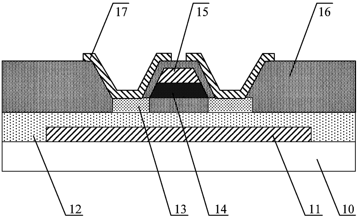
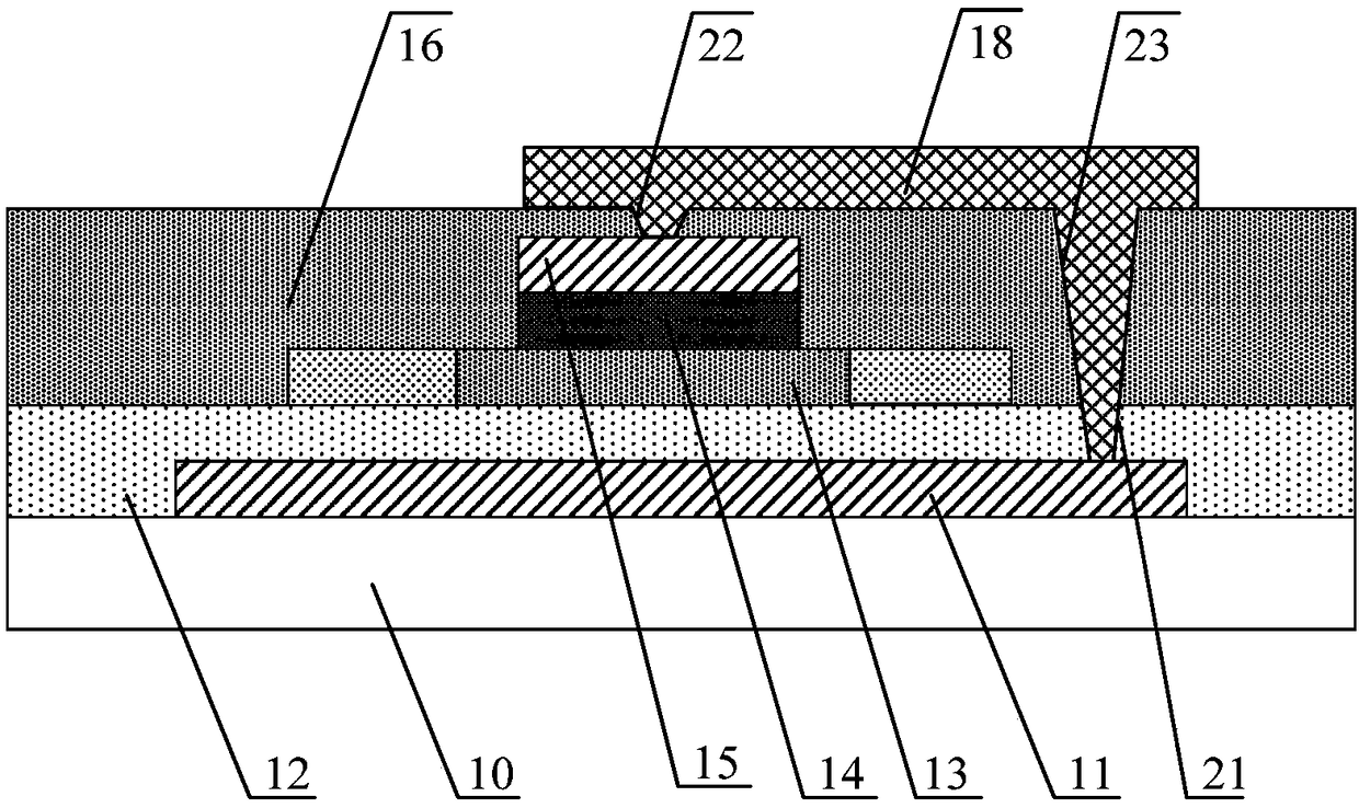
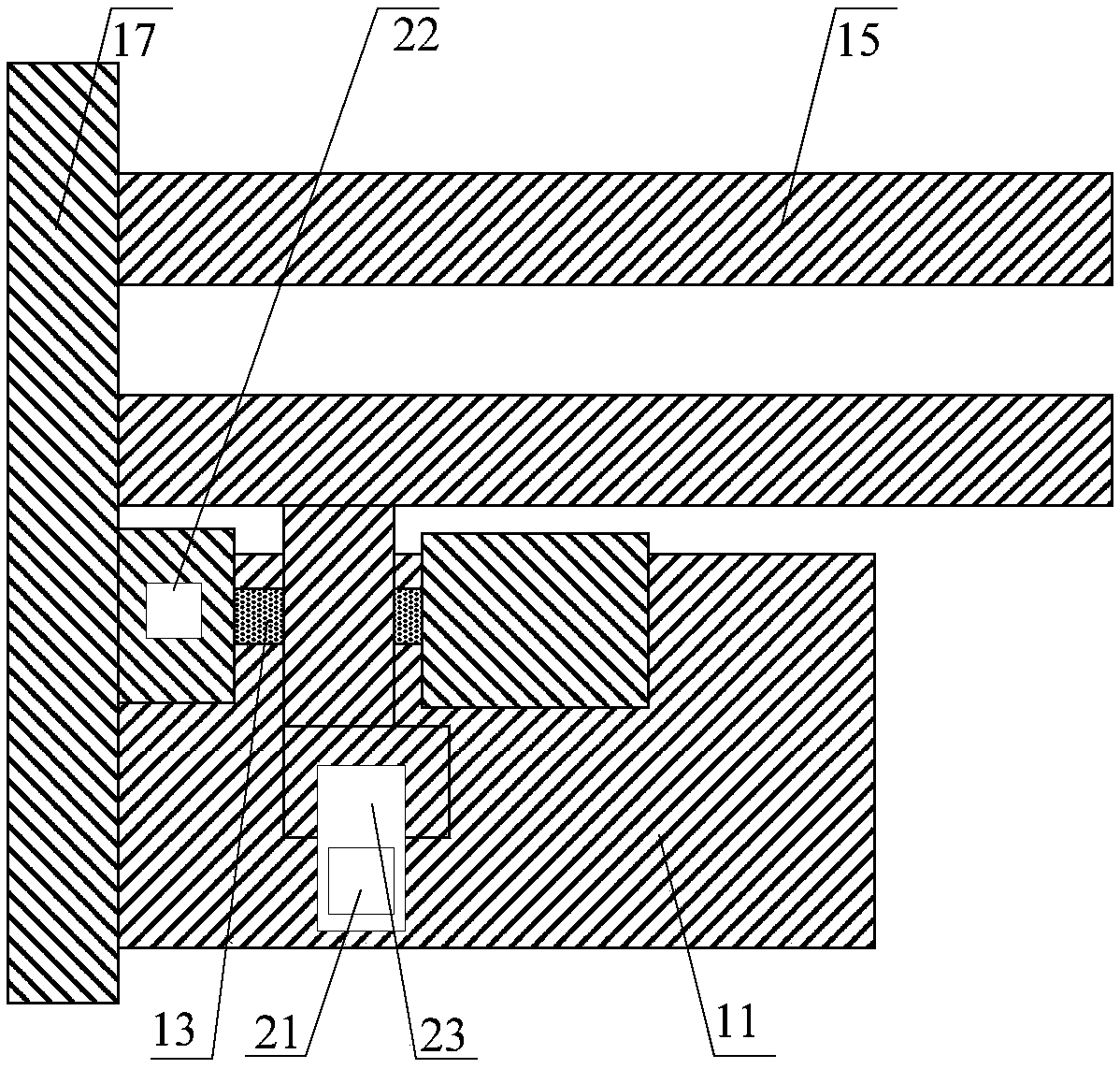
[0068] figure 1 Schematic structure of the thin film transistor provided for the embodiment of the present invention Figure 1 ;Such as figure 1 As shown, the thin film transistor provided by the embodiment of the present invention includes: a first gate 11 disposed on one side of the substrate 10 , an active layer 13 , a second gate 15 and source-drain electrodes 17 .
[0069] Wherein, the active layer 13 is arranged on the side of the first gate 11 away from the base substrate 10; the second gate 15 is arranged on the side of the active layer 13 away from the base substrate 10; the source and drain electrodes 17 are arranged on the second The side of the gate 15 away from the base substrate 10 ; the orthographic projection of the source and drain electrodes 17 on the base substrate 10 overlaps with the orthographic projection of the second gate 15 on the base substrate 10 .
[0070] It should be noted that, if figure 1 As shown, the thin film transistor provided by the em...
Embodiment 2
[0095] Based on the inventive concepts of the above embodiments, the embodiments of the present invention also provide a method for manufacturing a thin film transistor, Figure 5 The flow chart of the manufacturing method of the thin film transistor provided by the embodiment of the present invention, such as Figure 5 As shown, the manufacturing method of the thin film transistor provided in the embodiment of the present invention specifically includes the following steps:
[0096] Step 100, providing a base substrate.
[0097] Optionally, the base substrate may be a transparent insulating substrate, such as a glass substrate, a quartz substrate or other suitable substrates, which is not limited in this embodiment of the present invention.
[0098] Step 200, forming a first gate on one side of the substrate.
[0099] Optionally, the manufacturing material of the first gate may include copper-based metal, aluminum-based metal, and nickel-based technology. For example, the ...
Embodiment 3
[0153] Based on the inventive concepts of the above embodiments, the embodiments of the present invention further provide an array substrate, Figure 7 Schematic diagram of the structure of the array substrate provided for the embodiment of the present invention Figure 1 ,Such as Figure 7 As shown, the array substrate provided by the embodiment of the present invention includes a thin film transistor 1 and a photosensitive element 2 .
[0154] Wherein, the thin film transistor 1 is the thin film transistor provided in the first embodiment.
[0155] Specifically, the photosensitive element 2 is arranged on the side where the source and drain electrodes of the thin film transistor 1 are away from the substrate; the first electrode 2a of the photosensitive element 2 is connected to the source electrode or the drain electrode of the thin film transistor 1 .
[0156] Optionally, the photosensitive element 2 can be a PIN diode.
[0157] Optionally, as in Figure 7 As shown, th...
PUM
 Abstract
Description
Claims
Application Information
 - R&D
- Intellectual Property
- Life Sciences
- Materials
- Tech Scout
- Unparalleled Data Quality
- Higher Quality Content
- 60% Fewer Hallucinations
Browse by: Latest US Patents, China's latest patents, Technical Efficacy Thesaurus, Application Domain, Technology Topic, Popular Technical Reports.
© 2025 PatSnap. All rights reserved.Legal|Privacy policy|Modern Slavery Act Transparency Statement|Sitemap|About US| Contact US: help@patsnap.com


