

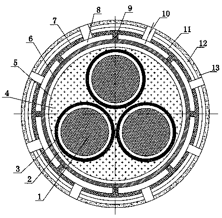
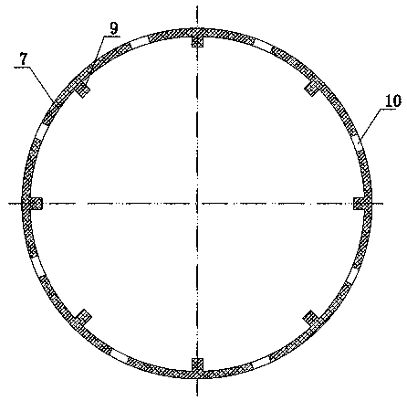
High-efficiency fire-resistant heat-dissipating cable
A cable and fire-resistant technology, which is applied in the field of power cables with flame retardant and high temperature resistance and efficient heat exchange, can solve the problem that the integrity of the cable structure and electrical performance cannot be guaranteed, the structure of the armored layer is not firm and stable, and the tensile resistance of the armored layer cannot be guaranteed. Compression strength drop and other problems, to achieve the effect of strict and reliable shielding, avoid wrinkles and contact gaps, and prolong the service life.
- Summary
- Abstract
- Description
- Claims
- Application Information
AI Technical Summary
Problems solved by technology
Method used
Image

Examples
Embodiment 1
[0028] The rare earth refractory layer material components include: 10 wt% of fluororubber, 6.8 wt% of aluminum hydroxide, 3 wt% of rare earth oxide, 1.5 wt% of glycerol, 3 wt% of silicon carbide, 3.6 wt% of lanthanum phosphate, zirconium Gadolinium acid 7.2 wt%, the rest is epoxy resin.
Embodiment 2
[0030] Rare earth refractory material components include: fluorine rubber 8 wt%, aluminum hydroxide 5 wt%, rare earth oxide 2 wt%, glycerol 1 wt%, silicon carbide 2 wt%, lanthanum phosphate 3 wt%, gadolinium zirconate 6 wt%, the remainder is epoxy resin.
Embodiment 3
[0032] Rare earth refractory material components include: fluorine rubber 12 wt%, aluminum hydroxide 8 wt%, rare earth oxide 4 wt%, glycerin 2 wt%, silicon carbide 4 wt%, lanthanum phosphate 6 wt%, gadolinium zirconate 8 wt%, the remainder is epoxy resin.
[0033] Another embodiment of the present invention has the same structure except that the rare earth refractory layer is coated with a rare earth water blocking layer. The material components of the rare earth water blocking layer include: 38 wt% epoxy resin, 6 wt% tung oil, 3 wt% rare earth oxide, 4 wt% magnesium oxide, 4.6 wt% zinc oxide, and the rest is nitrile rubber.
[0034] In the above embodiments, the rare earth oxyearth oxide is cerium oxide or lanthanum oxide.
PUM
| Property | Measurement | Unit |
|---|---|---|
| thickness | aaaaa | aaaaa |
| width | aaaaa | aaaaa |
| thickness | aaaaa | aaaaa |
Abstract
Description
Claims
Application Information